Table 4.4.3.7 value of variables – Yaskawa YASNAC PC NC Programming Manual User Manual
Page 270
4 - 133
YASNAC PCNC Programming Manual
Chapter 4: Enhanced Level Commands
By entering “’1.0” or “0.0” to the system variables indicated in Table 4.4.3.7, the corre-
sponding signals are output in the ON or OFF state.
Table 4.4.3.7
Value of Variables
•
If a value other than “1.0” or “0.0” is set for variables #1100 to #1131, it is treated as
indicated below.
<empty> or less than 0.5: 0.0
Other than above: 1.0
•
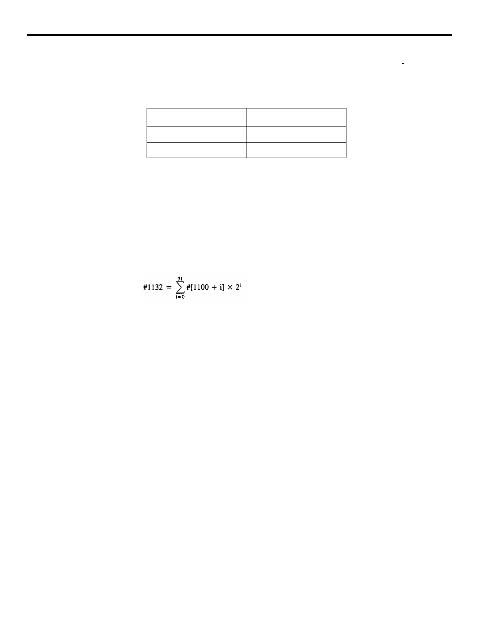
By entering system variable #1132 in the left side of an operation expression, it is pos-
sible to output the ON/OFF state to the 32 point output signals (U00 to U031) collec-
tively. In this case, a positive decimal value set for #1132 is output after converted
into a binary 32-bit value.
•
By entering system variables #1100 to #1132 in the right side of an operation expres-
sion, it is possible to read the ON/OFF state (1.0, 0.0, positive decimal value) output
last can be read.
(c) Offset amount and workpiece coordinate system distance
Tool offset amount can be read by entering system variables #12001 to #13199 in the right
side an operation expression.
Workpiece coordinate system shift distance (and workpiece coordinate system correction
amount) can be read by entering system variables #5201 to #5327, #7001 to #7947, and
#17821 to #19987 in the right side an operation expression.
By entering the system variables indicated above in the left side of an operation expres-
sion, it is possible to update the offset values.
Example of Programming
#116 = #12016:
Enters the content of tool offset number 16 to common variable
#116.
#5321 = #4:
Clears the workpiece coordinate system shift distance of X-axis and
sets the content of local variable #4.
Output Signal State
Variable Value
ON
1.0
OFF
0.0