Yaskawa YASNAC PC NC Programming Manual User Manual
Page 126
3 - 76
YASNAC PCNC Programming Manual
Chapter 3: Movement Control Commands
•
Upon completion of the execution of G39 block, the mode (M96/M97) selected
previously is recovered.
•
In the single-block mode, the cursor does not stop at the G39 block, but it stops at
the next block.
•
If interference is detected by the interference check function in the paths generated
by G39, G39 is disregarded and the tool paths are automatically corrected.
•
In the offset mode, intervention of MDI operation is not allowed. However, MDI
operation with one line of program is possible.
3.4.5
3-Dimensional Tool Offset Function (G40, G41, G42)*
By specifying G41 and G42, it is possible to shift the tool paths in the 3D vector direction.
(1) Commands
(a) Features of G40, G41, and G42
Table 3.4.5.1
G Codes Used for the Tool Offset Function
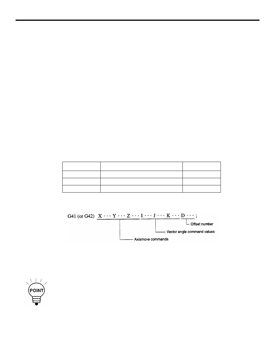
(b) Programming format
With the commands indicated above, the NC enters the 3-D tool offset mode and start-up
processing begins. The plane used for the 3-D tool offset is fixed to the XYZ plane.
Therefore, offset is not valid for additional axes. With G42, offset is made in the direction
opposite to the offset motion called by G41.
1. The start-up block (G41, G42) must contain all of I, J, K, and D. If any one of POINT
these addresses is not specified in the start-up block, the 2-D tool radius offset C is exe-
cuted.
•
If a D command is not specified, alarm 0162, “LACK OF ADDRESS” occurs. Alarm
0184 “RADIUS OFS CAL ERROR” occurs if “0” is set for all of I, J, and K.
G Code
Function
Group
G40
3-dimensional tool offset cancel
07
G41
3-dimensional tool offset, left
07
G42
3-dimensional tool offset, right
07