75 siemens, 75�1 siemens – Solare Datensysteme Solar-Log User Manual
Page 217
217
Siemens
Siemens
75 Siemens
75�1 Siemens
Easy Installation
Termination
Addressing
Interface
Yes
Resistor
Yes
RS485
Overview
•
Integrated interface
•
Where to connect: RJ45 socket on the bottom of the inverter
•
2-pin wiring
•
Communication address must be allocated.
•
Installation steps
•
Switch off the inverters and Solar-Log™
•
Connect inverters to the Solar-Log™
•
Connect the inverters to each other
•
Allocate communication address
Connect inverters to the Solar-Log™
To connect the Solar-Log™ and the inverters prepare cables with the following pin allocation.
Connecting the Solar-Log™ to the first inverter
Solar-Log™ (4/6 pin terminal plug)
First inverter - RS485 IN
(4-pin round plug)
Pin 1 (white)
Pin 2
Pin 4 (brown)
Pin 3
If only one inverter is to be connected this must be terminated (see following item "Bus termination").
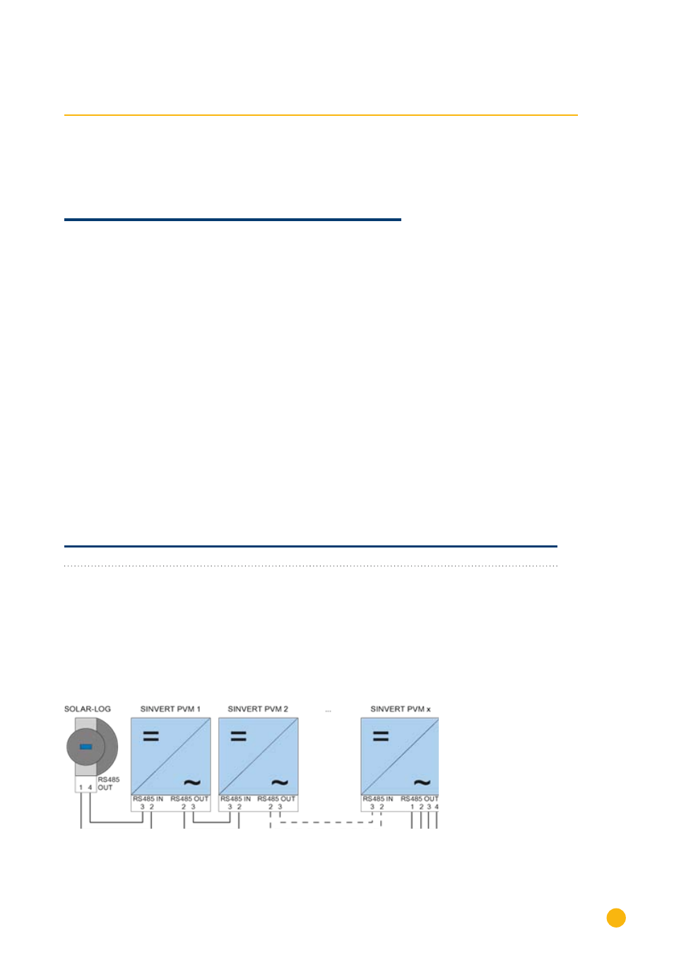
Connect the inverters to each other
Inverters must be connected to each other using shielded data cables via the RS485 connections located
on the SINVERT PVM.
The following illustration shows the main connection diagram.
Figure 12: Siemens – connecting inverters together