A-56, 2 ) non-procedual parameter list – Yaskawa MP2300S Basic Module User Manual
Page 378

Appendix G MSG-SND/MSG-RCV Functions (Ethernet)
G.1 Message Transmit Function (MSG-SND)
A-56
G.1.3 Message Transmit Function Parameter List (Param) Overview
The param of the MSG-SND function has a parameter list structure composed of 17 words. (The value of the Param
itself is the start address (MA, DA) of the parameter list.)
In the parameter list, enter a connection number, function code and its relevant parameter data. Process results and sta-
tus are also output.
When MEMOBUS or non-procedure is used as a communication protocol, the parameter list is as follows:
Note: Parameter details are explained in the parameter details for each protocol type. Refer to the following
items:
• G.1.4 Function Setting and Parameter Details for MEMOBUS and Extended MEMOBUS Protocols
• G.1.5 Function Setting and Parameter Details for MELSEC Protocol
• G.1.6 Function Setting and Parameter Details for MODBUS/TCP Protocol
• G.1.7 Function Setting and Parameter Details for Non-procedural Protocol
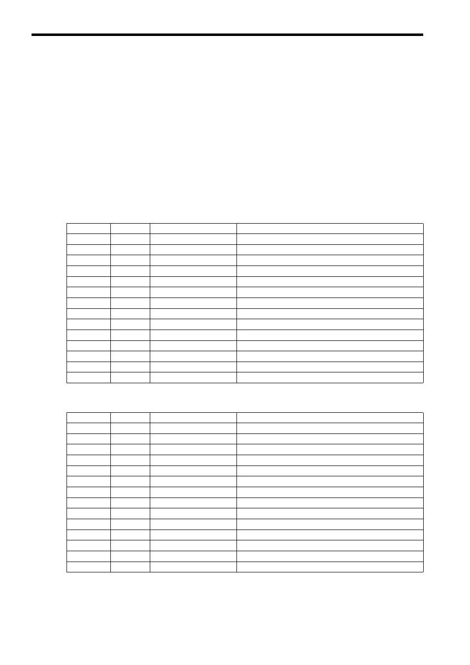
( 1 ) MEMOBUS Parameter List
Note: IN: Input, OUT: Output, SYS: For system use
( 2 ) Non-procedual Parameter List
Note: IN: Input, OUT: Output, SYS: For system use
Param No.
IN/OUT
Contents
Description
00
OUT
Process result
Process result is output.
01
OUT
Status
The status of the communication device is output.
02
IN
Connection number
Specifies the remote destination.
03
IN
Option
Sets a unique setting for each communication device.
04
IN
Function code
Sets a function code to transmit.
05
IN
Data address
Specifies the start address of the data.
06
IN
Data size
Sets the data size for a read/write request.
07
IN
Remote CPU number
Sets a remote CPU number.
08
IN
Coil offset
Sets the coil's offset word address.
09
IN
Input relay offset
Sets the offset word address of an input relay.
10
IN
Input register offset
Sets the offset word address of an input register.
11
IN
Holding register offset
Sets the offset word address of a holding register.
12
SYS
Reserved 1
−
13 to 16
SYS
Reserved 2
−
Param No.
IN/OUT
Contents
Description
00
OUT
Process result
Process result is output.
01
OUT
Status
The status of the communication device is output.
02
IN
Connection number
Specifies the remote destination.
03
IN
(unused)
−
04
IN
(unused)
−
05
IN
Data address
Specifies the start address of the data.
06
IN
Data size
Sets the data size for a write request.
07
IN
(unused)
−
08
IN
(unused)
−
09
IN
(unused)
−
10
IN
(unused)
−
11
IN
Register offset
Sets the offset word address of the register.
12
SYS
Reserved 1
−
13 to 16
SYS
Reserved 2
−