Jdip switch – Yaskawa MP930 User Manual
Page 106
System Startup
4.1.1 MC Unit
4 -4
D
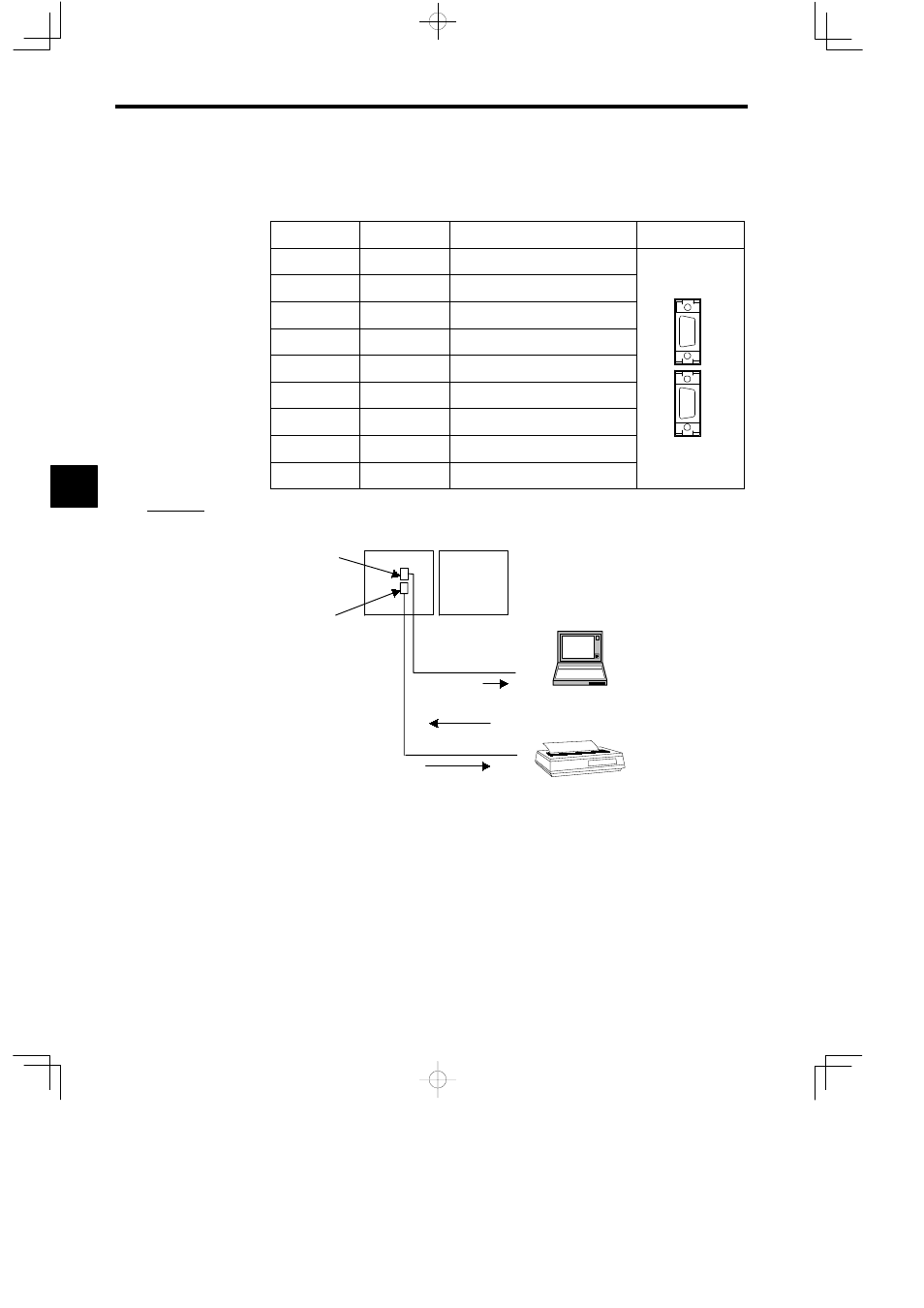
The MEMOBUS port connector is a D-sub connector (9-pin, female). Table 4.1 shows the
layout of the connector pins and the signal names.
Table 4.1 MEMOBUS Port Layout and Signal Names
Pin Number
Abbreviation
Signal Name
Appearance
1
FG
Protective ground
2
TXD
Transmission data
3
RXD
Reception data
4
RTS
Request to send
5
CTS
Clear to send
6
DSR
Data set ready
7
GND
Signal ground
8
−
9
DTR
Data terminal ready
D
The following illustration shows an example of the use of the MEMOBUS ports.
An ASCII Device (printer) can be connected to the port.
Port 1
MC Unit
I/O Unit
Communications using
commands/instructions
Data output
Programming Device
Monitor information
Communications using
MEMOBUS protocol
Programming information
Serial printer
Port 2
J
DIP Switch
D
The DIP switch consists of six pins. The pins are numbered 1 to 6, as shown in the diagram
in Table 4.2.
D
Each pin is ON when it is moved to the left.
4
A
EXAMPLE
"