Yaskawa MP930 User Manual
Page 198
5.1 Description of Parameters
5 -13
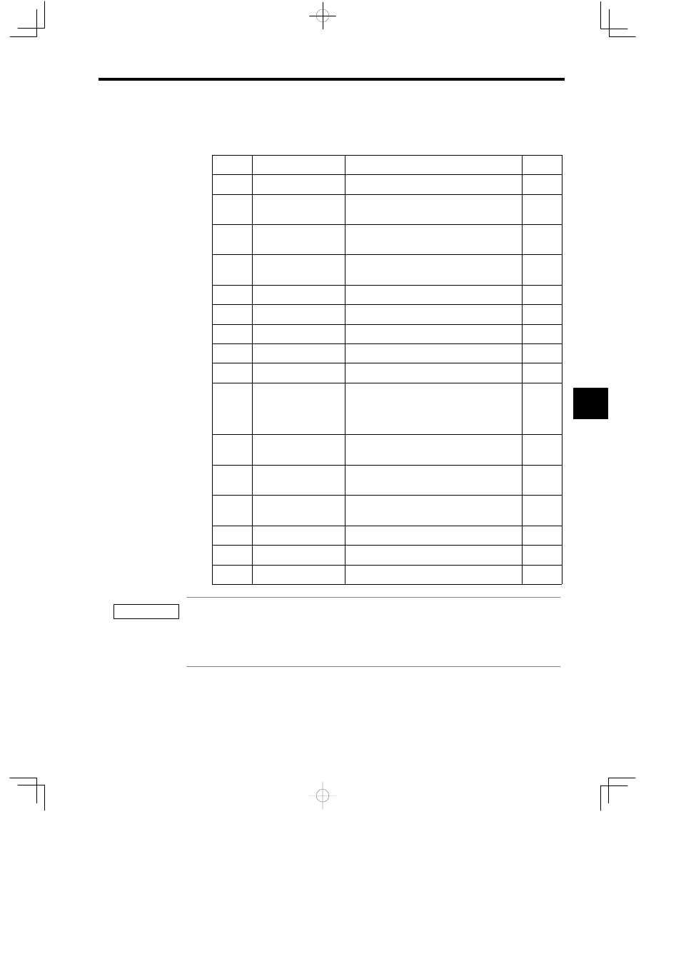
Cn-0014: Memory Switches 4
Cn-0014: The following table describes the bits in memory switches 4.
Bit
Name
Description
Default
0
−
−
0
1
Zero point return
direction
0: Forward
1: Reverse
0
2
P-SOT mask
0: P-SOT enabled
1: P-SOT disabled
0
3
N-SOT mask
0: N-SOT enabled
1: N-SOT disabled
0
4
−
−
0
5
−
−
0
6
−
−
0
7
−
−
0
8
−
−
0
9
Brake operation
0: Operate from the BRK-ON/BRK_OFF com-
mand
1: Operation from the Servopack (BRK-ON/
BRK_OFF disabled)
0
A
P-OT signal
0: Positive logic
1: Negative logic
0
B
N-OT signal
0: Positive logic
1: Negative logic
0
C
DEC signal
0: Positive logic
1: Negative logic
0
D
−
−
0
E
−
−
0
F
−
−
0
1.
Never change the default setting of bits with a dash (−) in the name column.
2.
Set bits 2 and 3 of Servopack user constant Cn-0014 to 1 to disable P-SOT and N-SOT.
3.
Set “1 : Operation from the Servopack” for brake operation. The brake signal is output in sequence with
Servopack ON/OFF.
5
IMPORTANT