Appearance of the mc unit i/o cable, Connection example of the mc unit i/o connector, System startup – Yaskawa MP930 User Manual
Page 118
Advertising
System Startup
4.2.4 Connector Pin Layout and I/O Circuits
4 -16
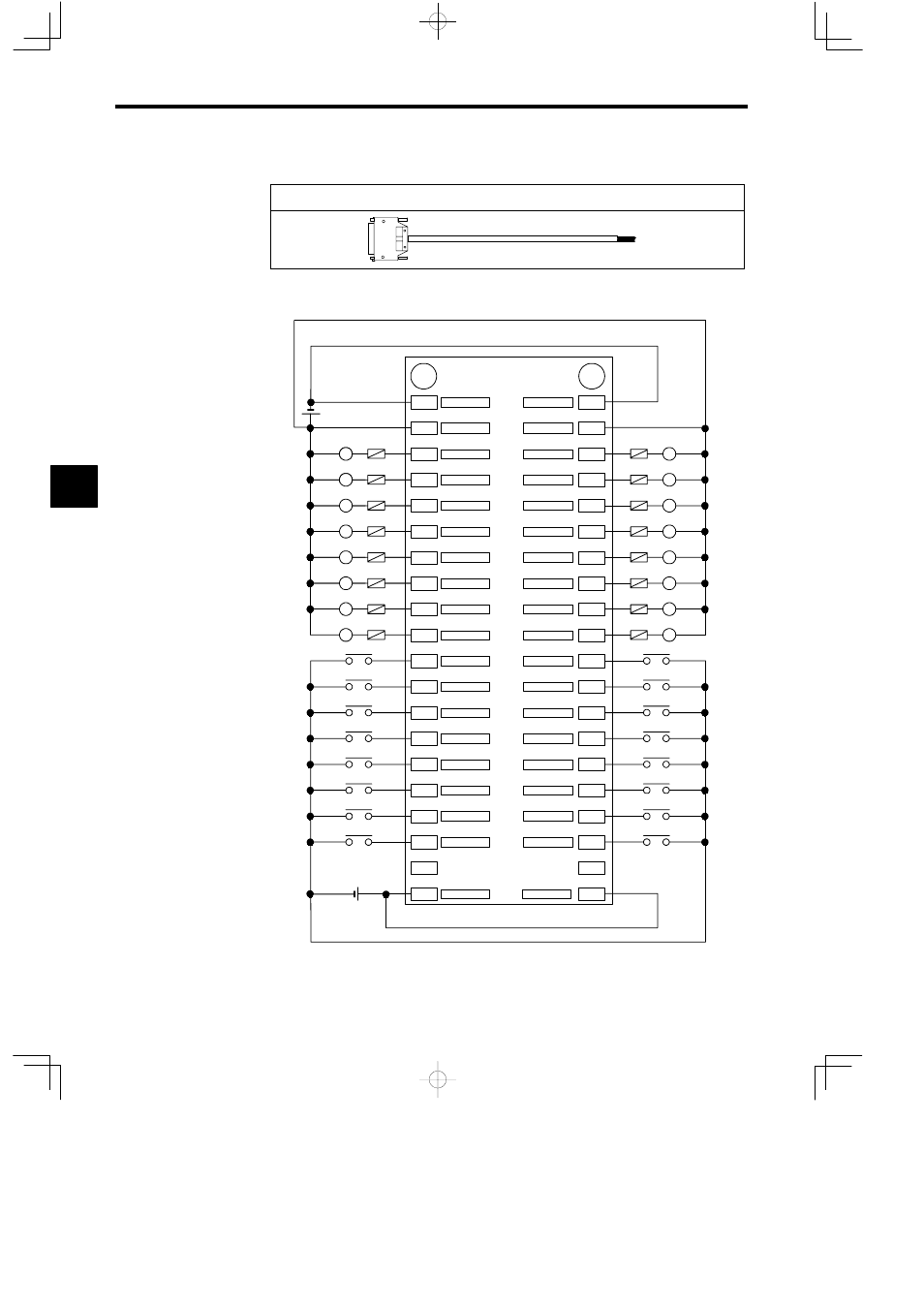
Appearance of the MC Unit I/O Cable
Model: JEPMC-W5410-jj
Connection Example of the MC Unit I/O Connector
L
L
L
L
L
L
L
L
A
1
2
3
4
5
6
7
8
9
10
11
12
13
14
15
16
17
18
19
20
Output 16
DCGND
DCPWR
Output 14
Output 12
Output 10
Output 8
Output 6
Output 4
Output 2
Input 16
Input 14
Input 12
Input 10
Input 8
Input 6
Input 4
Input 2
COMM
24 VDC
B
1
2
3
4
5
6
7
8
9
10
11
12
13
14
15
16
17
18
19
20
DCPWR
L
L
L
L
L
L
L
L
Output 15
Output 11
Output 9
Output 7
Output 5
Output 3
Output 1
Input 15
Input 13
Input 11
Input 9
Input 7
Input 5
Input 3
Input 1
COMM
Not used
Fuse
Load
24 VDC
Fuse
DCGND
Output 13
Load
4
Advertising
See also other documents in the category Yaskawa Equipment:
- Tag Generator (30 pages)
- MP3300iec (82 pages)
- 1000 Hz High Frequency (18 pages)
- 1000 Series (7 pages)
- PS-A10LB (39 pages)
- iQpump Micro User Manual (300 pages)
- 1000 Series Drive Option - Digital Input (30 pages)
- 1000 Series Drive Option - CANopen (39 pages)
- 1000 Series Drive Option - Analog Monitor (27 pages)
- 1000 Series Drive Option - CANopen Technical Manual (37 pages)
- 1000 Series Drive Option - CC-Link (38 pages)
- 1000 Series Drive Option - CC-Link Technical Manual (36 pages)
- 1000 Series Drive Option - DeviceNet (37 pages)
- 1000 Series Drive Option - DeviceNet Technical Manual (81 pages)
- 1000 Series Drive Option - MECHATROLINK-II (32 pages)
- 1000 Series Drive Option - Digital Output (31 pages)
- 1000 Series Drive Option - MECHATROLINK-II Technical Manual (41 pages)
- 1000 Series Drive Option - Profibus-DP (35 pages)
- AC Drive 1000-Series Option PG-RT3 Motor (36 pages)
- Z1000U HVAC MATRIX Drive Quick Start (378 pages)
- 1000 Series Operator Mounting Kit NEMA Type 4X (20 pages)
- 1000 Series Drive Option - Profibus-DP Technical Manual (44 pages)
- CopyUnitManager (38 pages)
- 1000 Series Option - JVOP-182 Remote LED (58 pages)
- 1000 Series Option - PG-X3 Line Driver (31 pages)
- SI-EN3 Technical Manual (68 pages)
- JVOP-181 (22 pages)
- JVOP-181 USB Copy Unit (2 pages)
- SI-EN3 (54 pages)
- SI-ET3 (49 pages)
- MECHATROLINK-III (35 pages)
- EtherNet/IP (50 pages)
- SI-EM3 (51 pages)
- 1000-Series Option PG-E3 Motor Encoder Feedback (33 pages)
- 1000-Series Option SI-EP3 PROFINET (56 pages)
- PROFINET (62 pages)
- AC Drive 1000-Series Option PG-RT3 Motor (45 pages)
- SI-EP3 PROFINET Technical Manual (53 pages)
- A1000 Drive Option - BACnet MS/TP (48 pages)
- 120 Series I/O Modules (308 pages)
- A1000 12-Pulse (92 pages)
- A1000 Drive Software Technical Manual (16 pages)
- A1000 Quick Start (2 pages)
- JUNMA Series AC SERVOMOTOR (1 page)
- A1000 Option DI-101 120 Vac Digital Input Option (24 pages)