5 connections to the servopack and motor, Jconnections to the sgd- jjj n servopack – Yaskawa MP930 User Manual
Page 123
4.2 Connection Methods
4 -21
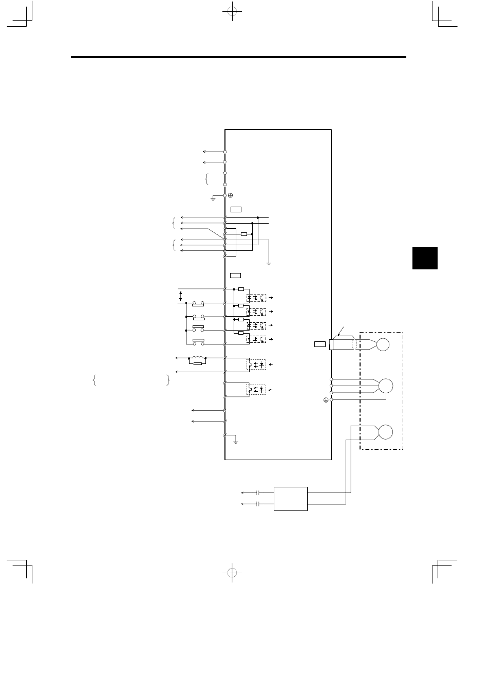
4.2.5 Connections to the Servopack and Motor
J
Connections to the SGD-jjjN Servopack
CN1
R
T
N
+24 V
+24 V
3.3 KΩ
N−LS
P−OT
6
7
N−OT
P−LS
DEC−LS
/DEC
/EXT
LATCH−LS
BAT(−)
BAT(+)
15
14
BRK
+24 V
0 V
CN3
CN2
M
PG
W
V
U
BR
BR
K
100 VAC
200 VAC
P
1
2
3
4
5
6
7
8
8
9
10
1
2
3
4
BRK
SG−BRK
ALM
SG−ALM
BAT
0⋅BAT
R1
T1
MECHATROLINK 1
MECHATROLINK 2
*2
To connect regenerative resistance
Servopack
SGD-jjjN
Forward drive prohibit limit switch
Reverse drive disable limit switch
Zero point return deceleration limit switch
Current position external latch/ZERO
Brake control relay
For absolute encoder
Backup battery
(To Battery Module)
The shield wire is connected to
the connector shell.
Forward drive prohibited
Reverse drive prohibited
Zero point return
deceleration limit
Brake control output
Alarm output
Be sure to connect the
shield wire at the end Unit.
Optical
encoder
Motor
Connector shell
Brake
Brake
power
supply
* 1. For details on MECHATROLINK connections,
see 4.2.4.
* 2. When a brake built into the motor or an external
brake is used, a BRK signal is received by the
relay and controls the brake.
* 3. Connected when an absolute encoder is used.
* 4. For zero point return methods 1 and 2, connect
ZERO signal (zero point LS) to /EXT signal.
*
1
*3
Current position
latch signals
Photocoupler output
Maximum operational voltage: 30 VDC
Maximum output current: 50 mA DC
*4
4