2 system connection example – Yaskawa MP930 User Manual
Page 111
Advertising
4.2 Connection Methods
4 -9
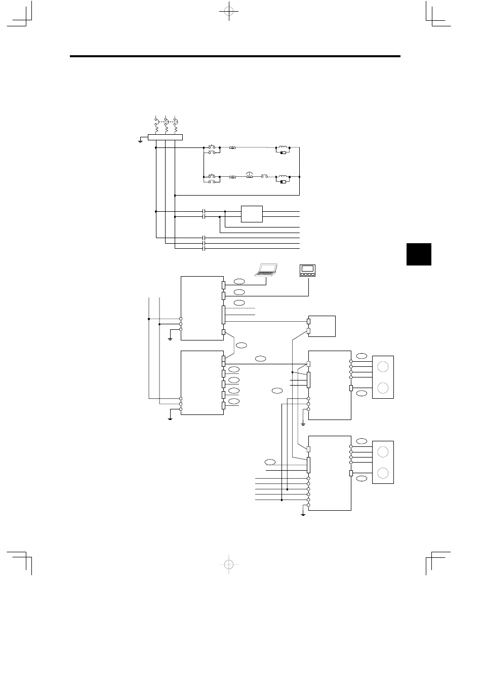
4.2.2 System Connection Example
The following illustration shows an example of the system connections used for the MP930.
1MCCB
R
S
T
2MC
SUP
2MC
1MC
1MC
SUP
1MC
1MC
2MC
+24 V
0 V
r
t
R1
S1
T1
+24 V
0 V
M
PG
M
PG
General inputs
General
outputs
General inputs
General outputs
r
t
R1
S1
T1
JEPMC-MC350
PORT 1
PORT 2
CN1
CN1
CN1
IN1
OUT1
IN2
OUT2
+24 V
0 V
FG
+24 V
0 V
FG
JEPMC-IO350
R
T
FG
2CN
U
V
W
FG
2CN
FG
3CN
1CN
3CN
1CN
U
V
W
r
t
R
S
T
FG
SGD-jjjN
SGDB-jjAN
J1
J1
J2
J3
J2
J2
J2
J2
J4
J5
J6
J6
J5
J7
J7
I/O
Noise filter
Control power
ON
Control power
OFF
Servo
power ON
Servo
power OFF
Emergency
stop
24-VDC
power
supply
Personal Computer
Programming Panel
Panel
General-purpose output
Absolute encoder battery module
(JRMSP-120XCP96000)
Mechanical inputs
Mechanical outputs
Mechanical in-
puts/outputs
General-purpose input
4
Advertising