Jdefining function i/o – Yaskawa MP930 User Manual
Page 83
Basic System Operation
3.5.2 Creating User Functions
3 -24
J
Defining Function I/O
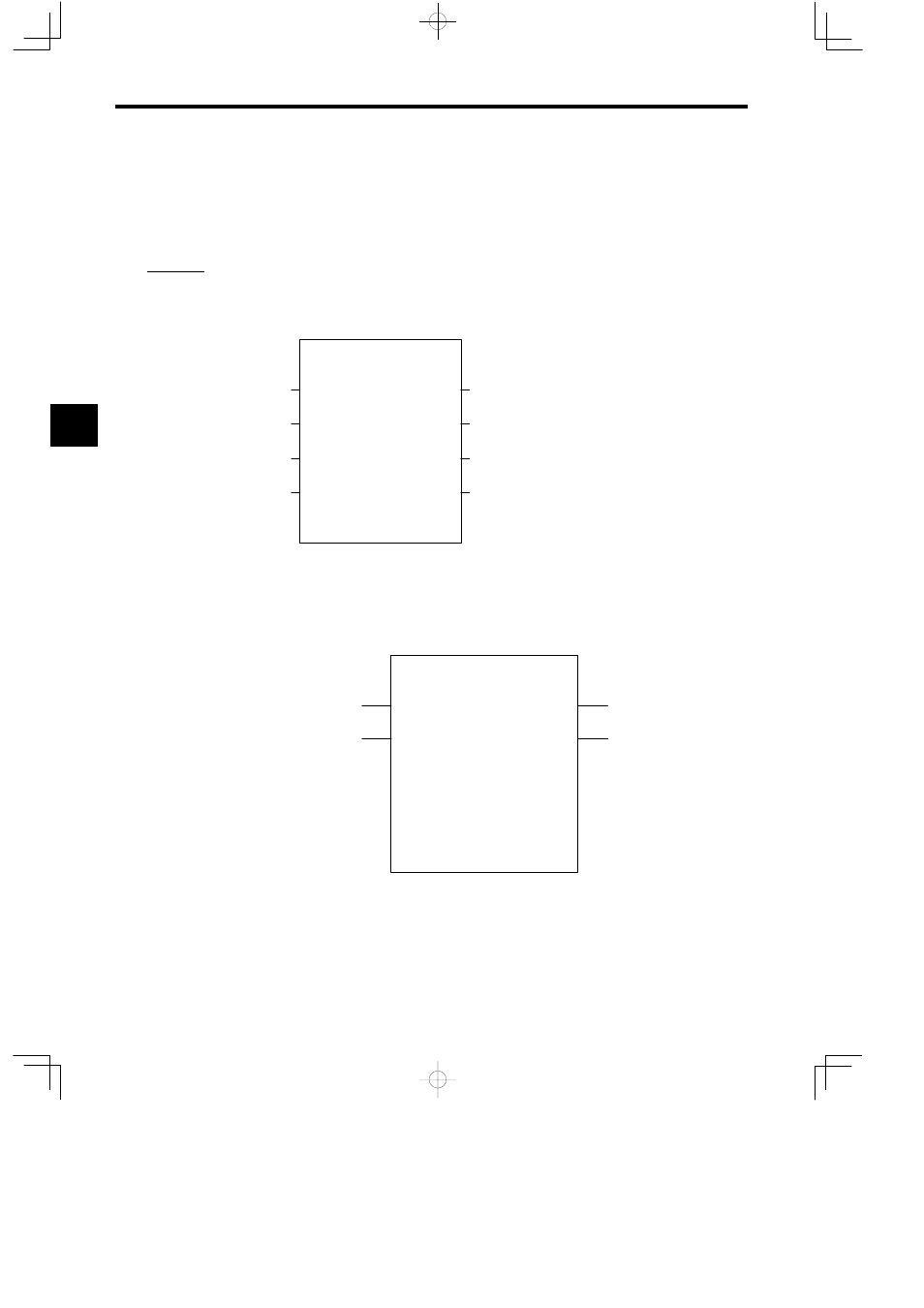
The function name and other specifications determined in the previous step are defined using
the CP-717. For details on operation methods, refer to the MP9jj Machine Controller Pro-
gramming Software User’s Manuals (SIEZ-C887-2.2-1, SIEZ-C887-2.2-2).
The following illustration shows the graphic representation of a function when the following
function is defined: Function name = TEST, number of inputs = 4, number of address inputs
= 1, and number of outputs = 4.
Note 1.
After creating the graphic representation of
the function, define the data types of the
functioninputs,outputs,andaddressinputs.
2. Threedatatypescanbedefined: Bit,integer,
and long integer.
3. When the data types aredefined, the system
automatically allocates inputs to the X regis-
ters, outputs to the Y registers, and address
inputs to the A registers.
TEST
IN_01
IN_02
IN_03
IN_04
IN_05
OUT_01
OUT_02
OUT_03
OUT_04
Figure 3.12 Graphic Representation of a Function 1 (Example)
The following illustration shows an example of the I/O definitions of a function.
Bit numeric input
Bit numeric output
Real number numeric input
Long integer numeric output
Integer numeric input
Integer numeric output
TEST
IN_01
IN_02
IN_03
IN_04
IN_05
OUT_01
OUT_02
OUT_03
OUT_04
BIT1
BIT2
FLT1
INT1
INT2
LNG1
BIT4
BIT3
===>
===>
===>
===>
Bit numeric input
Bit numeric output
ADR
Figure 3.13 Graphic Representation of a Function 2 (Example)
I/O signal addresses are automatically allocated from the highest signal on the graphic repre-
sentation. For the example given in Figure 3.13, the allocation of each I/O register will be as
shown in Table 3.10.
3
A
EXAMPLE
"