Yaskawa MP930 User Manual
Page 192
5.1 Description of Parameters
5 -7
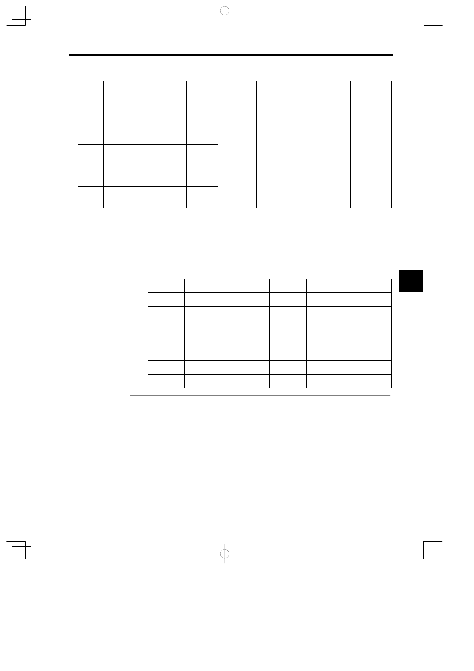
No.
Remarks
Meaning
Setting
Range
Register
No.
Name
28
−
IWxx30 to
IWxx37
−
Not used.
−
29
Encoder position at power OFF
(Low)
ILxx38
−2
31
to 2
31
−1
1 = 1 pulse
For ABS sys-
tem infinite
length position
30
Encoder position at power OFF
(High)
ILxx3A
length position
control
31
Absolute pulse position at power
OFF (Low)
ILxx3C
−2
31
to 2
31
−1
1 = 1 pulse
For ABS sys-
tem infinite
length position
32
Absolute pulse position at power
OFF (High)
ILxx3E
length position
control
Register Numbers
The address underlined in IWxx00 for each axis is the register number IWC000 in the Parameter Table with the
following offset added.
Offset for each axis = (Axis No. − 1) × 40H (64 words)
The leading address of the monitor parameters for each axis = Offset for each axis + IWC000
The following table lists the servo setting parameter register numbers for each axis.
Axis No.
IW Address
Axis No.
IW Address
1
IWC000 to IWC03F
8
IWC1C0 to IWC1FF
2
IWC040 to IWC07F
9
IWC200 to IWC23F
3
IWC080 to IWC0BF
10
IWC240 to IWC27F
4
IWC0C0 to IWC0FF
11
IWC280 to IWC2BF
5
IWC100 to IWC13F
12
IWC2C0 to IWC2FF
6
IWC140 to IWC17F
13
IWC300 to IWC33F
7
IWC180 to IWC1BF
14
IWC340 to IWC37F
5
IMPORTANT