Yaskawa MP930 User Manual
Page 85
Basic System Operation
3.5.2 Creating User Functions
3 -26
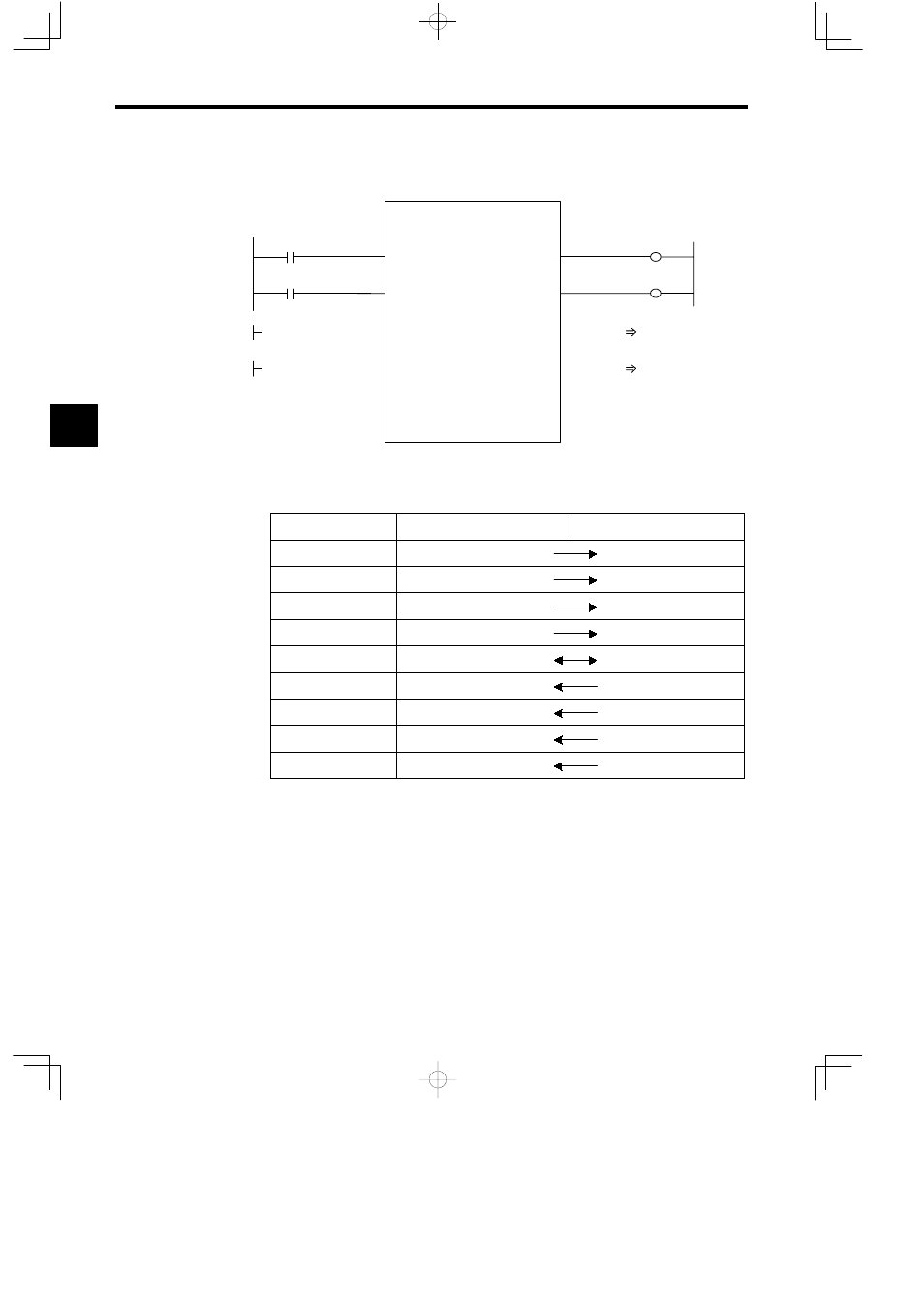
Example: I/O data is provided for the graphic representation as shown in the following il-
lustration.
TEST
BIT1
BIT2
FLT1
INT1
INT2
LNG1
BIT4
BIT3
===>
===>
===>
===>
ADR
DF00001
DW00003
DB000000
DB000001
DB000020
DB000021
DL00010
DW00012
MA00300
Figure 3.14 Graphic Representation for which Input Data is Provided (Example)
Table 3.11 Relationship Between I/O Data and Internal Function Registers
Name
I/O Data
Internal Function Register
BIT1
DB000000
XB000000
BIT2
DB000001
XB000001
FLT1
DF00001
XF00001
INT1
DW00003
XW00003
ADR
MA00300
AW00000
BIT3
OB00020
YB000000
BIT4
OB00021
YB000001
LNG1
DL00010
YL00001
INT2
DW0012
YW00003
In the table, address input register AW00000 is allocated to MA00300. That is, registers
AW00000, AW00001, and so on, used inside the TEST function correspond to external
registers MA00300, MA00301, and so on. Therefore, if a given value in AW00000 is
stored inside the function, this value will be stored in MA00300.
3