Yaskawa MP930 User Manual
Page 78
3.4 User Programs
3 -19
J
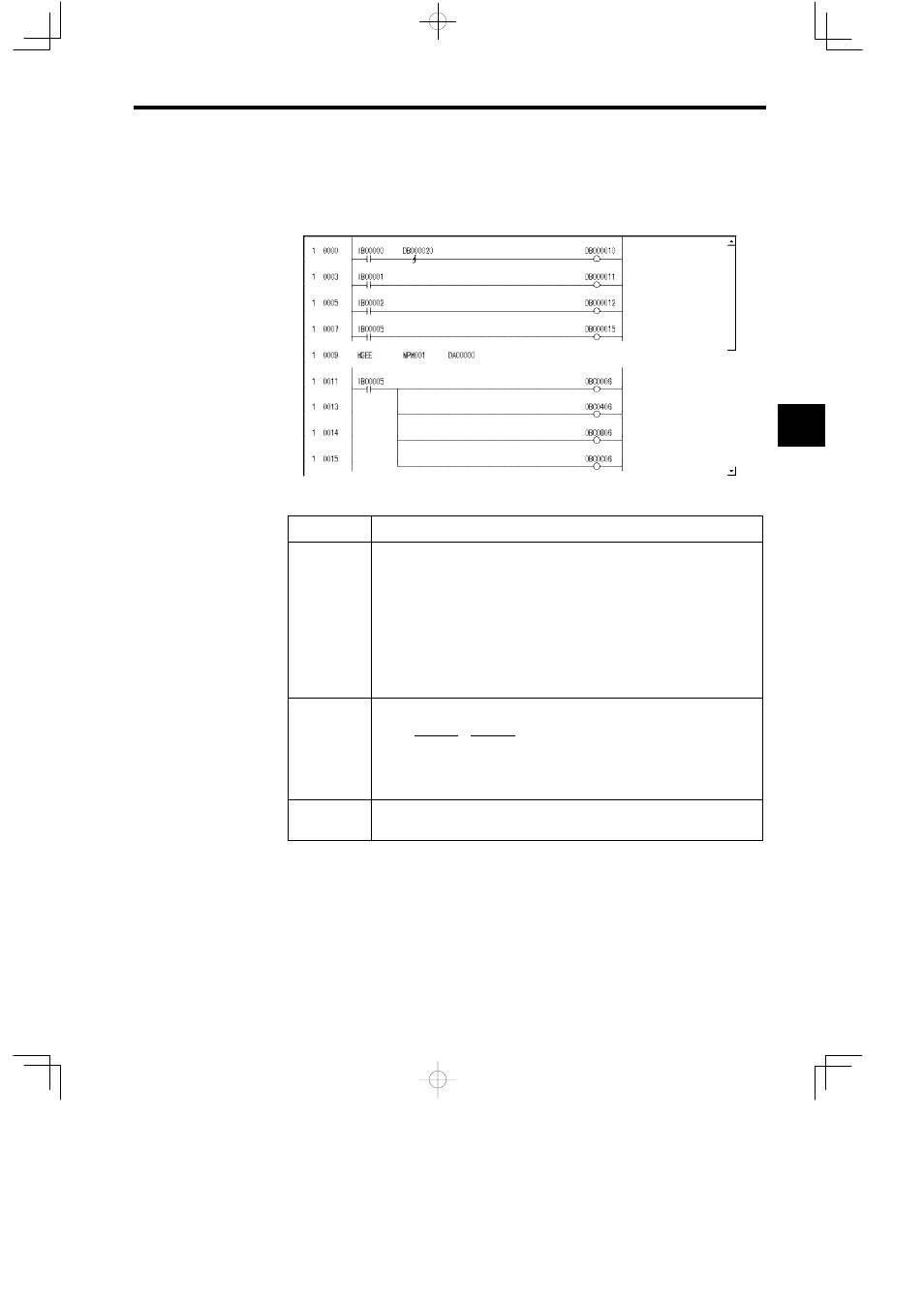
Example of a Ladder Logic Program for Motion Program Control
The minimum ladder logic program required to control a motion program is shown in the fol-
lowing illustration.
The contents of this ladder logic program are shown in the following table.
Step Number
Program Content
1 to 7
The signals connected to the MP930 external input signals are stored as the motion
program control signals.
IW0000 (external input signals) → DW00001 (second word of MSEE work regis-
ters)
S
Program operation start
S
Program pause
S
Program stop
S
Alarm reset
8
Calls motion program MP001
MSEE MPM001 DA00000
1
2
1.
Motion program number
2.
MSEE work register address
11 to 15
Resets the alarm (bit 6 of OWxx00) using the alarm reset signal (IB00005), and
clears the alarm for each axis.
When the external input signals (IB00000 to IB00007) connected to the MP930 are input to
DW00001 (second word of MSEE work registers) as motion program control signals using the
ladder logic program shown above, motion program operations such as run, stop and pause can
be performed by the system motion management functions.
3