Yaskawa Sigma II Indexer User Manual
Page 32
Sigma II Indexer User’s Manual
I/O Signals (CN1, CN4)
3-5
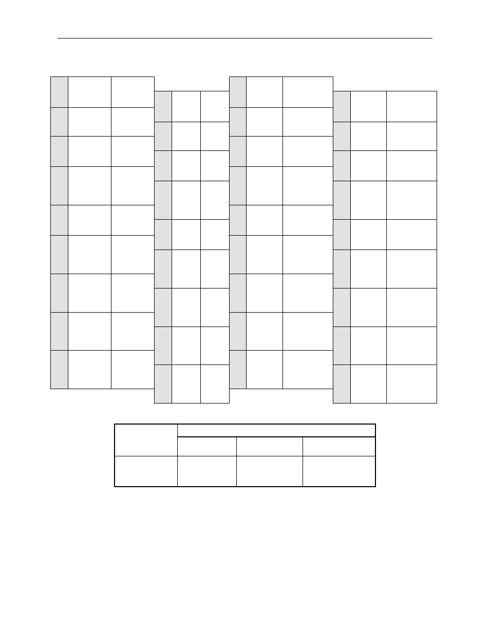
Table 3.2: CN4 Terminal Layout (Sigma II Indexer)
Table 3.3: CN1 Specifications (Servo Amplifier)
Note: Yaskawa P/N JZSP-CKI9 includes 3M connector and case.
1
24V/COM
External
input power
supply
19
/INPOSI-
TION+
In-position
output
2
-
-
20
/INPOSI-
TION-
In-position
output
3
/MODE 0/1
Mode select
input
21
/POUT0+
Programmable
Output 0
4
-
-
22
/POUT0-
Programmable
Output 0
5
/START-
STOP;
/HOME
Start-Stop/
Home input
23
/POUT1+
Programmable
Output 1
6
-
-
24
/POUT1-
Programmable
Output 1
7
/PGMRES;
/JOGP
Program
reset/Jog
forward
input
25
/POUT2+
Programmable
Output 2
8
-
-
26
/POUT2-
Programmable
Output 2
9
/SEL0;
/JOGN
Program
select 0/Jog
reverse input
27
/POUT3+
Programmable
Output 3
10
-
-
28
/POUT3-
Programmable
Output 3
11
/SEL1;
/JOG0
Program
select 1/Jog
select 0
input
29
/POUT4+
Programmable
Output 4
12
-
-
30
/POUT4-
Programmable
Output 4
13
/SEL2;
/JOG1
Program
select 2/Jog
select 1
input
31
-
-
14
-
-
32
-
-
15
/SEL3;
/JOG2
Program
select 3/Jog
select 2
input
33
-
-
16
-
-
34
-
-
17
/SEL4;
/JOG3
Program
select 4/Jog
select 3
input
35
-
-
18
-
-
36
-
-
Specifications for
Servo Amplifier
Receptacle
Applicable Mating Connector
Connector
Case
Manufacturer
10250–52A2JL or
Equivalent 50–pin
Right Angle
Receptacle
10150–3000VE
10350–52A0–008
Sumitomo 3M Co.