Yaskawa Sigma II Indexer User Manual
Page 52
Sigma II Indexer User’s Manual
Two-Step Trial Operation
4-7
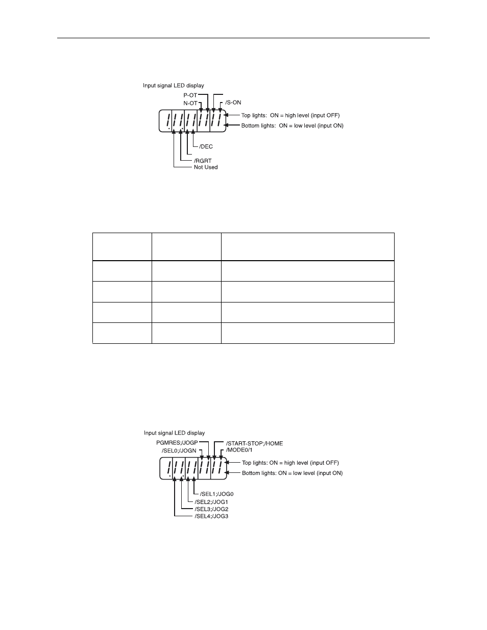
Turn ON and OFF each signal line to see if the LED monitor bit display on the panel
changes as shown below.
Note: The servomotor will not operate properly if the following signal lines are not wired correctly. Always
wire them correctly. Short the signal lines if they will be unused. The input signal selections (parame-
ters Pn803 to Pn80F) can be used to eliminate the need for external short circuiting.
7. Check CN4 input signals (if applicable)
Check input signal wiring in Monitor mode using a handheld digital operator via
CN7. Select monitor Un801 NS600 Input Signal Monitor. See Sigma II User’s Man-
ual 7.1.7 Operation in Monitor Mode for more details.
Note: CN1 and CN4 input signals can also be monitored by serial commands, IN1 and IN2, respectively, via
CN6. See 6 Serial Commands for serial communication specifications, command format, and serial
command descriptions.
Signal
Symbol
Connector Pin
No.
Description
P-OT
CN1-42
The servomotor can rotate in the forward
direction when this signal line is low (0V).
N-OT
CN1-43
The servomotor can rotate in the reverse
direction when this signal line is low (0V).
/S-ON
CN1-40
The servomotor is turned ON when this signal
line is low (0V). Leave the servomotor OFF.
+24VIN
CN1-47
Control power supply terminal for sequence
signals.
/SEL5
/SEL6