4 using the servo ready output signal – Yaskawa Sigma II Indexer User Manual
Page 75
Sigma II Indexer User’s Manual
Sequence I/O Signals
5-20
Set the brake timing used when the servo is turned OFF by input signal /S-ON (CN1-
40) or when an alarm occurs during motor operation.
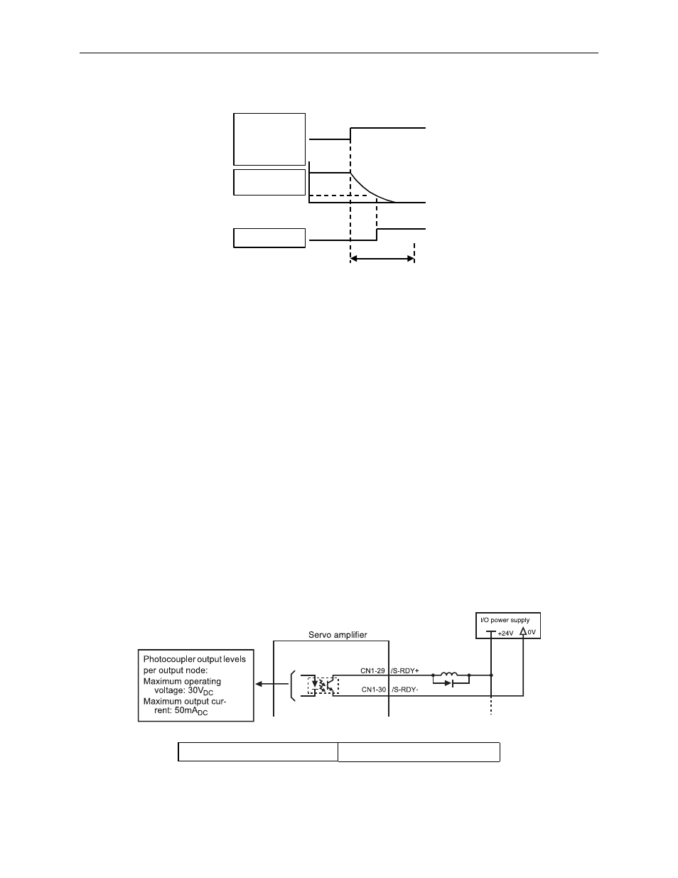
Figure 5.9 Holding Brake Setting
Brake ON timing when the servomotor stops must be adjusted properly because ser-
vomotor brakes are designed as holding brakes. Adjust the parameter settings while
observing equipment operation.
/BK Signal Output Conditions During Servomotor Operation
The circuit is open under either of the following conditions:
• Motor speed drops below the setting at Pn507 after servo OFF.
• The time set at Pn508 has elapsed since servo OFF.
The actual speed used will be the maximum speed even if Pn507 is set higher than
the maximum speed.
5.3.4 Using the Servo Ready Output Signal
The basic use and wiring procedures for the Servo Ready (/S-RDY) output signal
(photocoupler output signal) are described below.
Servo Ready means there are no servo alarms and the main and control circuit power
supply is turned ON.
/S-RDY CN1-29, 30
Servo Ready Output Signal
/S-ON input
Power OFF by
/S-ON (CN1-40)
input or alarm
occurrence
Motor speed
(rpm)
Pn-507
/BK output
Stop by dynamic brake
or coast to a stop.
(Pn001.0)
Pn508
Release
brake
Servo ON
Hold with brake
Servo OFF
Output
o