Table 5.3: input signal specifications (cn1, cn4) – Yaskawa Sigma II Indexer User Manual
Page 68
Advertising
Sigma II Indexer User’s Manual
Sequence I/O Signals
5-13
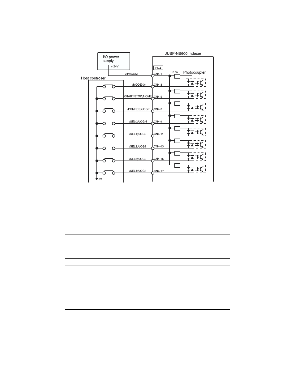
Input Signal Connections (CN4)
Connect the sequence input signals as shown below.
Figure 5.4 Input Signal Connections (CN4)
Note: Provide a separate external I/O power supply; neither the servo amplifier or Sigma II Indexer have an
internal 24V power supply.
Table 5.3: Input Signal Specifications (CN1, CN4)
Item
Specification
Inputs
CN1: /S-ON, /SEL5, P-OT, N-OT, /DEC, /SEL6, /RGRT
CN4: /MODE0/1, /START-STOP;/HOME, /PGMRES;/JOGP, /SEL0;/JOGN,
/SEL1;/JOG0, /SEL2;/JOG1, /SEL3;/JOG2, /SEL4;/JOG3
Input Format Sinking or Sourcing
Isolation
Optical
Voltage
11 to 25 VDC
Input Imped-
ance
3.3 k
:
Current
Rating (ON)
8 mA maximum
OFF Current 0.1 mA maximum (OFF Voltage = 1.0 V)
Ω
Advertising
See also other documents in the category Yaskawa Equipment:
- Tag Generator (30 pages)
- MP3300iec (82 pages)
- 1000 Hz High Frequency (18 pages)
- 1000 Series (7 pages)
- PS-A10LB (39 pages)
- iQpump Micro User Manual (300 pages)
- 1000 Series Drive Option - Digital Input (30 pages)
- 1000 Series Drive Option - CANopen (39 pages)
- 1000 Series Drive Option - Analog Monitor (27 pages)
- 1000 Series Drive Option - CANopen Technical Manual (37 pages)
- 1000 Series Drive Option - CC-Link (38 pages)
- 1000 Series Drive Option - CC-Link Technical Manual (36 pages)
- 1000 Series Drive Option - DeviceNet (37 pages)
- 1000 Series Drive Option - DeviceNet Technical Manual (81 pages)
- 1000 Series Drive Option - MECHATROLINK-II (32 pages)
- 1000 Series Drive Option - Digital Output (31 pages)
- 1000 Series Drive Option - MECHATROLINK-II Technical Manual (41 pages)
- 1000 Series Drive Option - Profibus-DP (35 pages)
- AC Drive 1000-Series Option PG-RT3 Motor (36 pages)
- Z1000U HVAC MATRIX Drive Quick Start (378 pages)
- 1000 Series Operator Mounting Kit NEMA Type 4X (20 pages)
- 1000 Series Drive Option - Profibus-DP Technical Manual (44 pages)
- CopyUnitManager (38 pages)
- 1000 Series Option - JVOP-182 Remote LED (58 pages)
- 1000 Series Option - PG-X3 Line Driver (31 pages)
- SI-EN3 Technical Manual (68 pages)
- JVOP-181 (22 pages)
- JVOP-181 USB Copy Unit (2 pages)
- SI-EN3 (54 pages)
- SI-ET3 (49 pages)
- MECHATROLINK-III (35 pages)
- EtherNet/IP (50 pages)
- SI-EM3 (51 pages)
- 1000-Series Option PG-E3 Motor Encoder Feedback (33 pages)
- 1000-Series Option SI-EP3 PROFINET (56 pages)
- PROFINET (62 pages)
- AC Drive 1000-Series Option PG-RT3 Motor (45 pages)
- SI-EP3 PROFINET Technical Manual (53 pages)
- A1000 Drive Option - BACnet MS/TP (48 pages)
- 120 Series I/O Modules (308 pages)
- A1000 12-Pulse (92 pages)
- A1000 Drive Software Technical Manual (16 pages)
- A1000 Quick Start (2 pages)
- JUNMA Series AC SERVOMOTOR (1 page)
- A1000 Option DI-101 120 Vac Digital Input Option (24 pages)