Yaskawa Sigma II Indexer User Manual
Page 79
Sigma II Indexer User’s Manual
Sequence I/O Signals
5-24
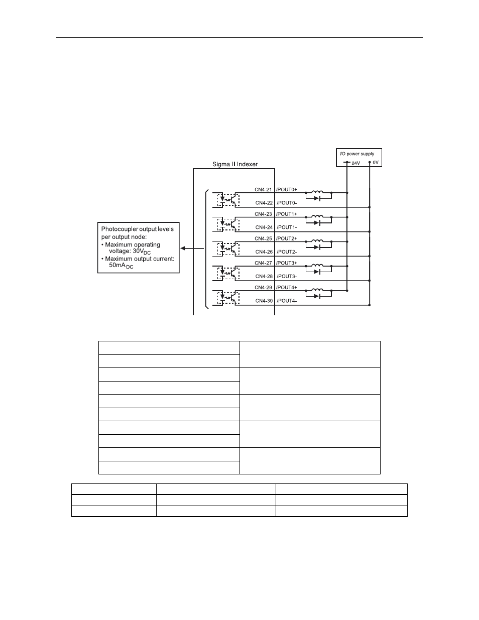
5.3.7 Using the Programmable Output Signals (/POUT0 ~ /POUT4)
The basic use and wiring procedures for the programmable output signals (/POUT0
~ /POUT4) are described below. The outputs can be used in either program table
mode or serial mode operation. Refer to 5.7.4 Program Table Set-Up and 6.5 Serial
Command Functions for more information.
/POUT0+ CN4-21
Programmable Output 0
/POUT0- CN4-22
/POUT1+ CN4-23
Programmable Output 1
/POUT1- CN4-24
/POUT2+ CN4-25
Programmable Output 2
/POUT2- CN4-26
/POUT3+ CN4-27
Programmable Output 3
/POUT3- CN4-28
/POUT4+ CN4-29
Programmable Output 4
/POUT4- CN4-30
/POUT0 ~ /POUT4 State
State
Result (default state)
ON
Output Closed or Low Level
Output Active
OFF
Output Closed or High Level
Output Non-Active
Output
o
Output
o
Output
o
Output
o
Output
o
Output
o
Output
o
Output
o
Output
o
Output
o