5 absolute encoder reception sequence, Warning – Yaskawa Sigma II Indexer User Manual
Page 97
Sigma II Indexer User’s Manual
Absolute Encoders
5-42
5.6.5 Absolute Encoder Reception Sequence
A host device can be used to monitor the absolute encoder feedback. The sequence
in which the servo amplifier receives data from the absolute encoder and transmits
them to the host device is shown below.
Be sure you understand this section when designing a host device to monitor the
absolute encoder feedback.
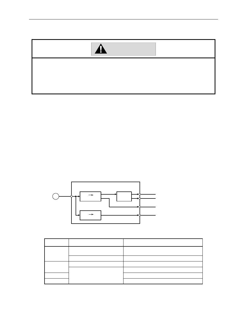
Outline of Absolute Signals
The absolute encoder’s outputs are PAO, PBO, PCO, and PSO signals as shown
below.
The multi-turn limit value should be changed only for special applications.
Changing it inappropriately or unintentionally can be dangerous.
If the Multi-turn Limit Value Disagreement Alarm occurs, check the setting of parameter Pn205 in the servo amplifier to be
sure that it is correct. If Fn013 or MLTLIMSET is executed when an incorrect value is set in Pn205, that same incorrect value
will be set in the encoder. There will not be an additional alarm, even if an incorrect value is set, but incorrect positions will
be detected.
This results in a potentially dangerous situation where the machine will move to an unexpected position.
Signal
Status
Contents
PAO
Initial State
Serial data
Initial incremental pulse
Normal State
Incremental pulse
PBO
Initial State
Initial incremental pulse
Normal State
Incremental pulse
PCO
Home position pulse
PSO
Rotation count serial data
WARNING
Servo amplifier
PS
PAO
PBO
PCO
PSO
PG
Serial data
pulse conversion
Data data
conversion
Dividing
circuit
(Pn201)