Yaskawa Sigma II Indexer User Manual
Page 99
Sigma II Indexer User’s Manual
Absolute Encoders
5-44
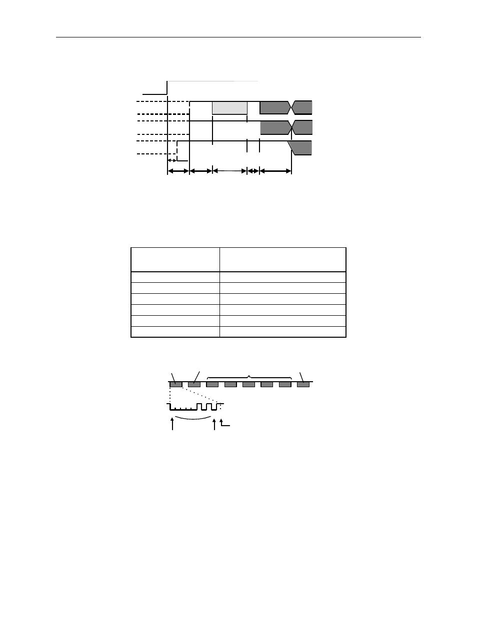
4. The system enters a normal incremental operation state approximately 50ms
after the last serial data is received.
Detailed Signal Specifications
PAO Serial Data Specifications
The number of revolutions is output in five digits.
Note: 1.
Data is “P+00000” (CR) or “P-00000” (CR) when the number of revolutions is zero.
2.
The revolution range is “+32767” to “-32768.” When this range is exceeded, the data change
from “+32767” to “-32768” or from “-32768” to “+32767”
PSO Serial Data Specifications
The number of revolutions and the absolute position within one revolution are
always output in five and seven digits, respectively. The data output cycle is approx-
imately 40ms.
Data Transfer Method
Start–stop Synchronization
(ASYNC)
Baud rate
9600bps
Start bits
1 bit
Stop bits
1 bit
Parity
Even
Character code
ASCII 7–bit code
Data format
8 characters, as shown below.
SEN signal
PAO
PBO
PSO
Incremental pulses
Incremental pulses
Rotation count serial data
Initial incremental pulses
Undefined
Undefined
Undefined
50 ms
60ms minimum
90ms typical
260ms maximum
10ms
max.
Approx. 15ms
1 to 3ms
25ms maximum
Rotation count
serial data
Initial
incremental pulses
(Phase A)
(Phase A)
(Phase B)
(Phase B)
Power
0 0 0 0 0 1 0 1 0
Data
Start bit
Even parity
1
Stop bit
“P” “+” or “-” “0” to “9” “CR”