Yaskawa Sigma II Indexer User Manual
Page 73
Sigma II Indexer User’s Manual
Sequence I/O Signals
5-18
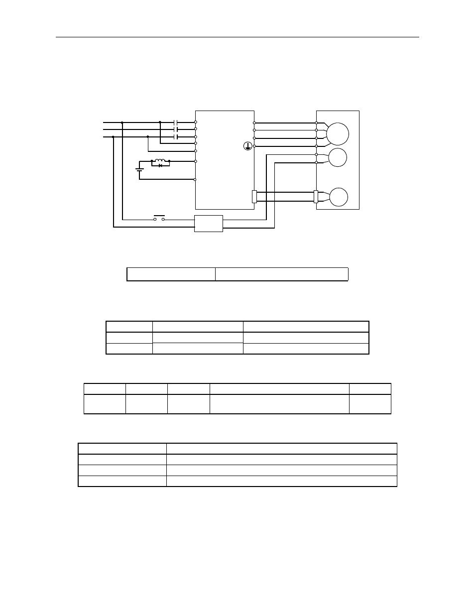
Wiring Example
Use the servo amplifier output signal /BK and the brake power supply to form a
brake ON/OFF circuit. The following diagram shows a standard wiring example.
Figure 5.8 Wiring Example
This output signal controls the brake when using a servomotor with a brake and does
not have to be connected when using a servomotor without a brake.
The following parameter is used to set the state of /BK output.
Related Parameters
/BK
Brake Interlock Output
State
Status
Result (default state)
ON:
Output Closed or low level
Releases the brake.
OFF:
Output Open or high level
Applies the brake.
Parameter
Signal
Pin No.
Setting
Default
Pn817
/BK
CN1-27, 28
0 = Output Closed = Releases the brake.
1 = Output Open = Releases the brake.
0
Parameter
Description
Pn506
Time Delay from Brake Reference until Servo OFF
Pn507
Speed Level for Brake Reference Output during Motor Operation
Pn508
Timing for Brake Reference Output during Motor Operation
M
BK
PG
Servomotor
with brake
A (1)
B (2)
C (3)
D (4)
E (5)
F (6)
U
V
W
CN2
Red
Black
Blue or
yellow
White
AC
DC
BK-RY
BK-RY
+24V
Brake Power Supply
Power supply
Servo amplifier
L1
L2
L3
L1C
L2C
CN1-27
CN1-28
/BK+
/BK-
27
Output
o