Yaskawa J50M Instructions User Manual
Page 108
2.11.5 VARIABLES (Cent’d)
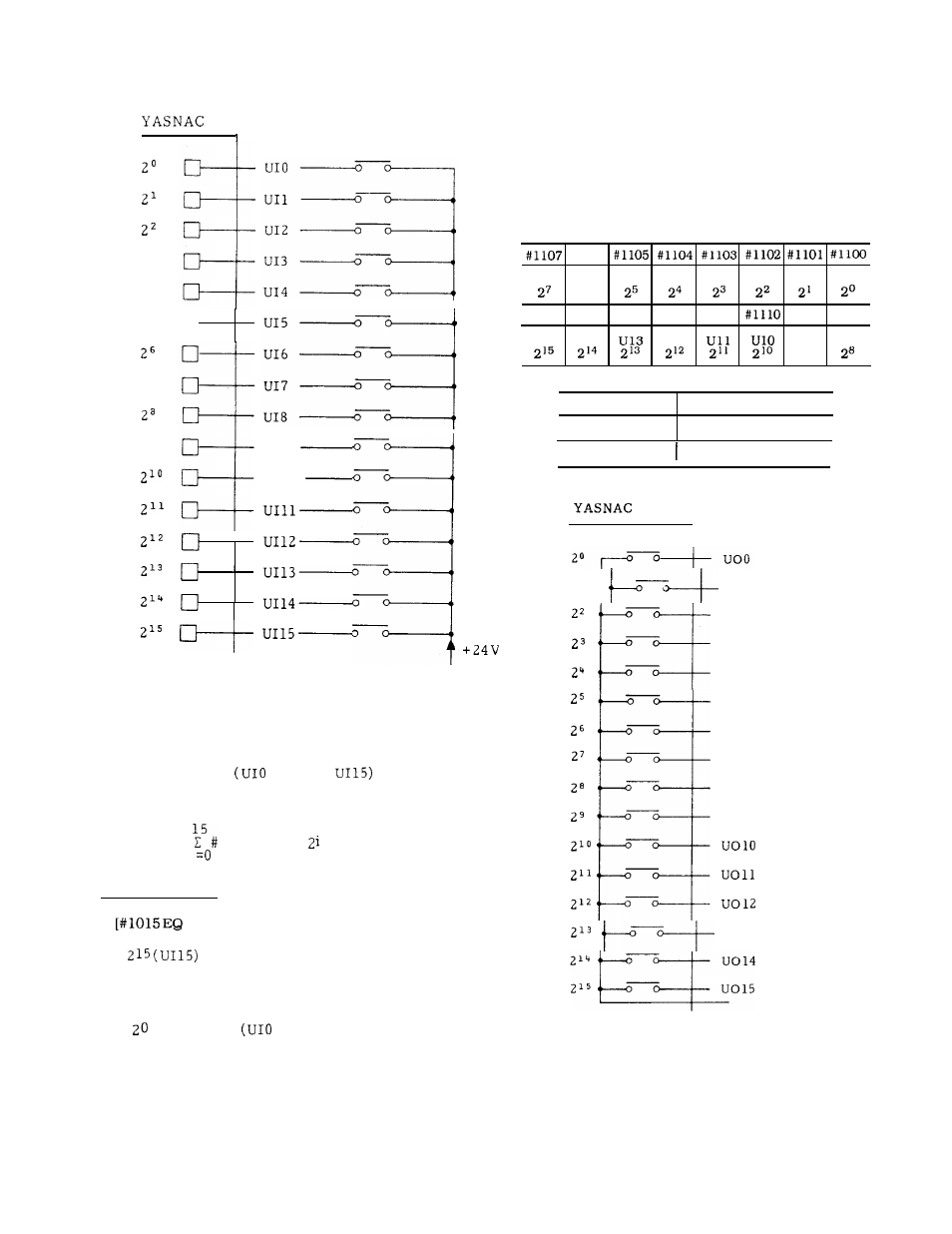
B. Interface Output Signals (#1100 through #11 15,
#1132)7
23
24
25
27
29
•1
I
I
Each read variable is
I
I
U19
UI1O
1. 0
or O. 0 when the asso-
ciated contact is “closed” or “open” respectively,
regardless of the unit system of the machine.
b.
When system variable #1032 is designated,
the input signals
through
that consist
of 16 points (16 bits) are collectively read as a
decimal positive value.
#1032 =
[1000 + i] *
i
Sample Program
IF
O] GOTO 100 ;
Bit
is read and, if it is “O, ” a
branch is made to sequence number N1OO.
#130 = #1032 AND 255
Bits
through 27
through U17) are
collectively read to be stored in common
variable #130 as a decimal positive value.
Note:
System variables #1000 through #1032 can-
not be placed to the left-hand of operational ex-
pressions.
1 0 0
a.
When one of system variables #1100 through #1115
is specified to the left-hand of an operational expression,
an on/off signal can be sent to each of user-macro-dedi-
cated 16-point output signals. The relationships between
the output signals and the system variables are as shown
below :
#1 106
U07
U06
U05
U04
U03
U02
Uo 1
Uoo
26
#1115 #1114 #1113 #1112
#1111
#1 109 #1108
U15
U14
U12
U09
U08
29
Variable Value
Output Signal
1
Contact Closed
o
C o n t a c t O p e n
21
’
01
U02
Uo 3
Uo
4
Uo
5
—
U06
U07
U08
U09
’
013
When 1.0 or 0.0 are substituted in any of #1100
through #1115, the associated output contact is
output in the “closed” or “open’’state.