Yaskawa J50M Instructions User Manual
Page 15
2.3.2
SIMULTANEOUSLY CONTROLLABLE AXES OF
THREE-AXIS CONTROL
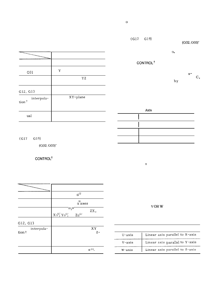
Table 2. 5 shows simultaneously controllable
axes.
Table 2.5 Simultaneously Controllable Axes of
Three-axis Control
(1) The
axis represents any one of axes A, B, C,
U, V or W, selected as the 4th axis.
(2) Circular arc plane is determined according to
the currently effective G codes for plane desig-
n a t i o n
to
. For details, refer to
2.9.4, “ CIRCULAR INTERPOLATION
on page 22.
(3) For circular interpolation axis
any one of
linear axes U, V , and W should be designated.
2.3.4 4TH
AXIS
An additional 4th axis can be incorporated. In
this manual, the 4th axis is referred to as
axis, and represents any of the 6 axes, A, B,
U, V and W.
Address. is specified
parameter
#6023.
2.3.4.1 ROTARY AXIS (A, B OR C AXIS)
The rotary axis is defined as follows.
Table 2.7 Rotary Axes for 4th
Control Table
Simultaneously
controllable axes
Positioning GOO
X, Y and Z axes
Linear interpola-
tion
Circular inter-
polation G02, G03
X,
and Z axes
Two axes:
X Y ,
or ZX
(see Note. )
Circle cutting+
Two axes: X and Y
Circle in
and linear
feed in Z-axis direction .
Refer to 2. 9.5 HELICAL
INTERPOLATION .
Helical
G02, G03
X. Y and Z
Man
control
Rotary axis
Definition
A axis
Rotar y axis parallel to X-axis
Note:
Circular arc plane is determined according to the
currently effective G codes for plane designation.
to
For details, refer to 2.9.4, “ CIRCULAR INTER-
P O L A T I O N
on page 22.
2.3.3
SIMULTANEOUSLY CONTROLLABLE AXES OF
FOUR-AXIS
Table 2. 6 shows simultaneously controllable
axes.
Table 2.6 Simultaneously Controllable Axes of
Four-axis Control
B axis
Rotary axis parallel to Y-axis
C axis
Rotary axis parallel to Z-axis
N o t e :
In this manual, any one of the three
axes, A, B and C, is referred to as
B-axis .
The unit of output increment and input increment
for B-axis is “deg. instead of “mm” used with
linear axes.
For the other respects, the treat-
ments are the same as those in mm.
(Metric
system)
Even when inch system is selected by parameter,
the values for the B- axis remains “deg. “ unit.
The control does not convert B-axis coordinate
commands.
However, feedrate command F is
converted. (Refer to 2.9.3. “ LINEAR INTERPO-
L A T I O N ” )
Simultaneously
controllable axes
X, Y, Z, and
axes
Positioning GOO
Linear interpola-
tion GO 1
Circular inter-
polation G02, G03
Circular cuttingt
X, Y, Z , and
Two axes,
X Y , Y z ,
or
2.3.4.2 LINEAR AXIS (U,
AXIS)
The linear axes are defined as follows.
Table 2.8 Linear Axes
Two axes: X and Y
Linear axis
I
Definition
Helical
G02, G03
Three axes :
circle in
-
plane and linear feed in
Linear axis parallel to X-axis
Linear axis
to Y-axis
Linear axis parallel to Z-axis
axis direction.
Refer tc
2. 9.5 HELICAL INTERPO-
LATION on page 27.
Manual control
Four axes, X, Y, Z, or
N o t e :
In this manual, linear axes either U, V
or W are indicated by c-axis.
7