Yaskawa J50M Instructions User Manual
Page 61
B . Where extension or reduction is applied to
an axis in the preceding block and the start
point has already been offset, the total move-
ment value is identical to that described a-
bove, but the distance is measured from the
offset start point.
With a command same as that described above :
‘0”’”)
100.
START
POINT
END POINT
(TOOL MOVEMENT)
Offset value by preceding block
Fig. 2.57
Note:
Where the tool offset value is larger
than the programmed movement value,
the direction of movement may be re-
versed when extension or reduction
is applied.
7.
8.
G46 X1O.
D1O ;
D1O = 20.
END POINT START POINT
(TOOL MOVEMENT)
F i g .
2.58
The above applies to X- andY-axis, butG45
to G48 may also be programmed to
Z-axis
in
the same manner.
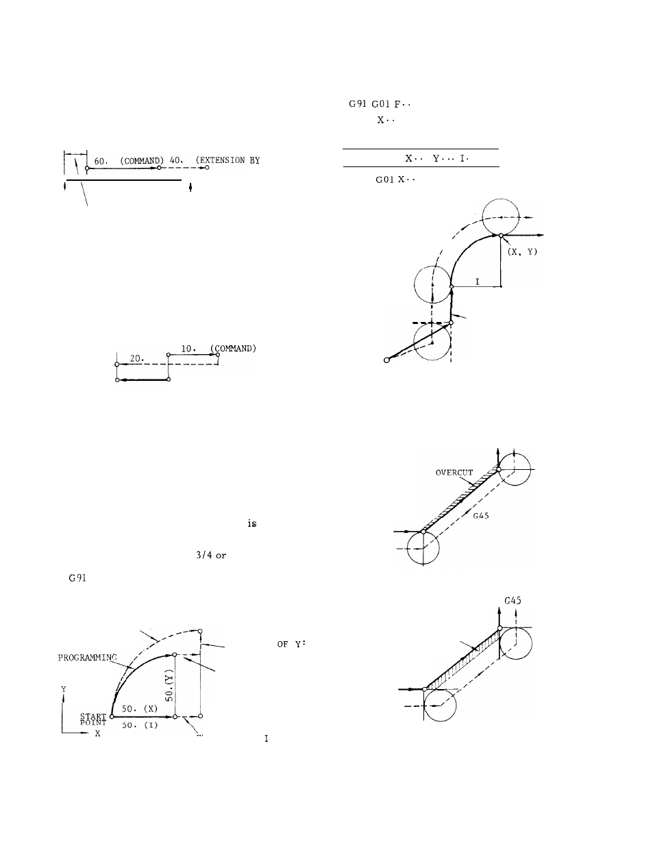
Application to circular interpolation
If I, J, K are programmed in the block with
G45 to G48, extension or reduction
made
respectively in the same directions as X, Y,
z .
Therefore, tool radius compensation is
possible with 1/4 circle,
full circle.
G45 G02 X50.
Y50.
150.
D1O ;
D1O = 20.
MOVEMENT OF
TOOL
,
X T E N
S
ION
/
‘
—
20.
/’
EXTENSION OF X:
20.
EXTENSION OF :
20.
In practice , correct radius compensation of
circular arc is made if an offset is applied
in the preceding block.
. ;
G46
. Y.. . D1O ;
G45 Y.. . ;
G45 G02
.
. . ;
. ;
TOOL MOVEMEN<
/’
CENTER
PROGRAMMING
START POINT
Note:
When it is necessary to program 1/2
circle , assemble them using 1 /4 circle.
Fig.
2.60
(a)
UNDERSIZE
CUT
G45
(b)
Fig.
2.59
Fig. 2.61
53