Yaskawa J50M Instructions User Manual
Page 167
How to Edit Control-Out and Control-In
The control-in and control-out part
by the usual edit operation.
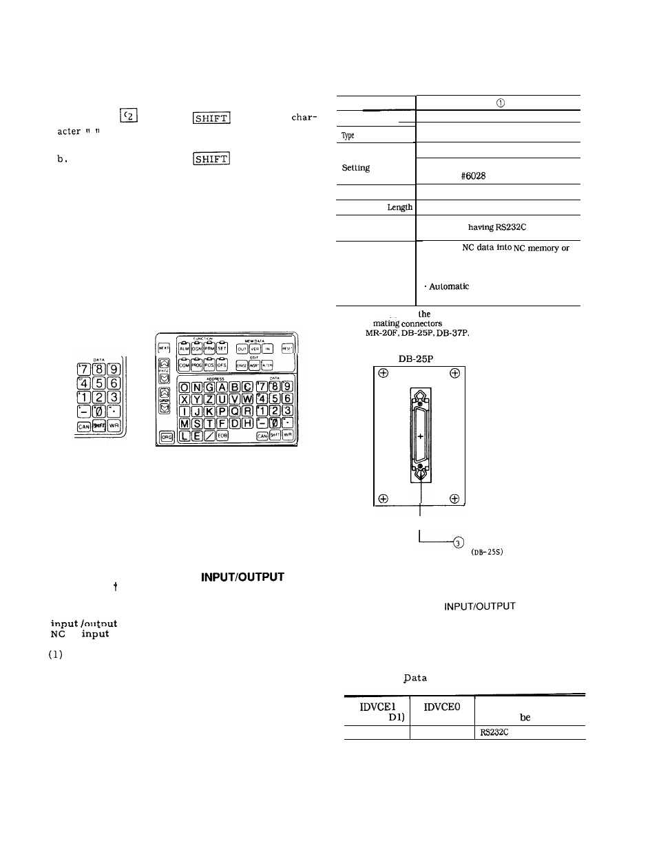
4.7.1 TYPES AND FUNCTIONS OF INTERFACE
Table 4.1
RS232C Interface No. 1
may
be edited
key, and
a, D e p r e s s
key and
Name
of
Interface
of Interface
Parameter
Connector (Note)
(
may
be entered.
Depress
❑
key and
Serial voltage interface
Parameter setting
Input : #6026
Output :
DB-25S
key, and char-
acter “)” may be entered.
Notes:
15 m
Equipment
interface
. Storing
collating them.
. Outputting NC data to external
equipment (punch out).
operation in the tape
mode (for tape reader).
Max
Cable
External
Equipment
1.
The characters which are indicated in the
thick-lettered keys shown below may be enclosed
in control–out and control-in.
2.
The number of characters that may be en-
closed in control-out and control-in less than
32.
Functions
3.
Nesting of the control-out and control-in is
not allowed.
Note : The types of
connector on the NC side.
For the
to this connector, use the follow-
ing :
F i g .
4.38
Characters Enclosed
in Control-Out and
C o n t r o l - I n ( T h i c k -
Lettered Keys) for
9“ CRT
I
RS232C INTERFACE
Fig. 4.39 Data 1/0 Interface Receptacles
in Control Cabinet
4.7
SUPPLEMENT TO DATA
INTERFACE
4.7.2
SETTING OF DATA
INTERFACE
TO BE USED
The external equipment having the designated
interface may be attached to the
To use data input/output interface, it is neces
-
sary to set which interface is to be used. Make
this setting as follows:
(2)
(3)
to
/output the foilowing NC information:
Part Programs
Tool Offset Amount
Setting and Parameters
(1) Setting of
Input Interface to Be Used
Data Input Interface
(#6003,
(#6003, DO)
to
used
o
1
Interface
N o t e :
PT R interface is for the standard tape
r e a d e r .
Usually, this interface is set.
159