Yaskawa J50M Instructions User Manual
Page 47
4.
Movement in compensation mode
When after the tool radius compensation is
programmed by G41, G42, the tool moves along
the offset path until the instruction G40 is
g i v e n .
As talc
of the path is automatically
made by the control, designate only the
shape of the
in the program. The
tool path is controlled as follows depending
on the angle between blocks.
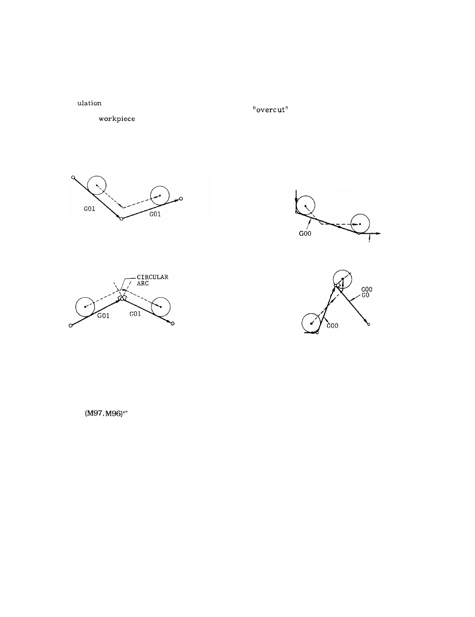
A .
Inside corner ( 180° or less) :
Intersection computing type
Fig. 2.35
B .
Outside corner (over 180°) :
Circular path type (in the case of M96)
Fig. 2.36
In this case, movement of circular path is
included in the former block.
M96 . . .
Tool radius compensation circular
path ON
M97 . . .
Tool radius compensation circular
path OFF (execution of intersection
computation)
Normally, M96 is used for this operation,
h o w e v e r , when there is a possibility of an
in cutting special shapes with the
M96, M97 should be used.
c .
Movement in GOO mode
The instruction GOO positions tools independ-
ently along each axis toward the final offset
position.
Care should be taken on the cutter
path.
G
OO
OR
GO1
OR
GO1
/
00
(In
M96 mode)
Fig. 2.37
Code M97 can be used to machine the outside cor-
ner by the intersection computation, depending on
the work. For details, refer to 2.8.6, “CIRCULAR
PATH MODE ON/OFF ON TOOL RADIUS COMPEN-
SATION C
on page 17.
39