Yaskawa J50M Instructions User Manual
Page 35
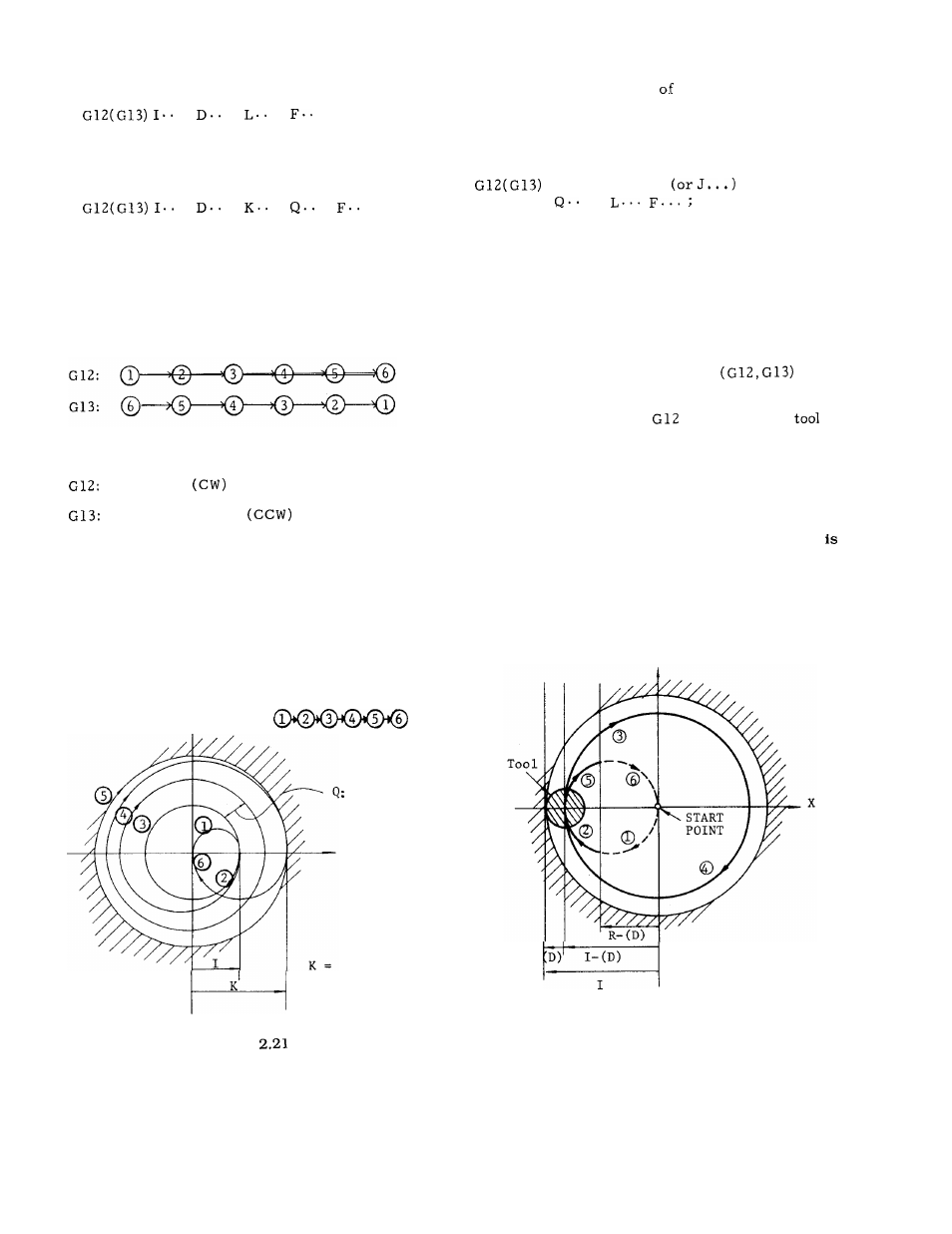
Commanding repeated circle designation
.
.
.
. ;
With this command, the circular bore surface
can be executed L times.
Commanding spiral circle Q, K
.
.
.
.
. ;
With this command, the tool is moved along a
spiral before finally finishing a circular hole,
as shown below.
For the sake of simplification,
the diagram shows the tool path with a zero
radius (D = O) .
Q (radius increment) must be
programmed without sign.
Tool path
(D) represents a set value of tool radius
compensation.
I :
R :
D:
F:
Clockwise
Counterclockwise
Radius of finished circle
(incremental value with sign)
Rapid traverse section
(incremental value with sign)
Tool radius compensation No.
Cutting feed rate
Y
I
G12:
RADIUS
INCREMENT
x
RADIUS OF
FINISHED CIRCLE
Combined designation
rapid traverse sec-
tion, repeated circle and spiral circle.
Rapid traverse section, repeated circle desig-
nation and spiral circle can be commanded in
combination as shown below.
I . . . D . . . R . . .
K . . .
.
Notes :
Circle cutting is possible only on the XY plane.
The tool speed in the rapid traverse section is
set by parameter #6225.
Feedrate override cannot be applied to rapid
traverse rate.
While dry run switch is ON, the
tool speed conforms to dry run speed.
With a circle cutting command
, the
tool is offset for its radius compensation with-
out the use of G41 or G42 (tool radius compen-
sation) .
When using
or G13, cancel
radius compensation with G40.
In the explanation above, only motions in the +
direction of X-axis is considered. With proper use of
signs for I, K and D codes, motions in the - direction
of X-axis (symmetrical with respect to Y-axis) can be
commanded. In Fig. 2.23, signs of I, R and (D) are
minus. However, cutting in the Y-axis direction
impossible.
I, J, K, R, Q and L codes in circle cutting com-
mand are effective only in the block containing
them.
Y
Fig. 2.22
Fig.
27