Yaskawa J50M Instructions User Manual
Page 152
4.3.4.2
C U R R E N T P O S I T I O N D I S P L A Y ( E X T E R -
N A L ) : P O S I T I O N ( E x T E R N A L )
Move commands will be summed and displayed.
G92, if issued, does not affect the display.
To reset this screen, depress the ORG key after
designating an axis with the ADDRESS key. The
current position along the designated axis will be
reset to “O”.
Resetting operation is available in any
mode and even during operation.
These displaying and resetting operations are
the same
with the case of POSITION( UN
SAL) #6005D5 = O (Position obtained by simple
summation) .
the resetting operation is
effective only to the displayed screen since
there are independent position registers.
The data displayed in
mode are the same
as those displayed on the “ 3–axis/4-axis exter-
nal position display” (option) . You may con-
sider that the coordinate data of POSITION
(
E X
T
E
R
N A L
) are transmitted to the outside
as they are unchanged.
Fig. 4.20 Current Position Display
( External) -Example (with 4-axis control)
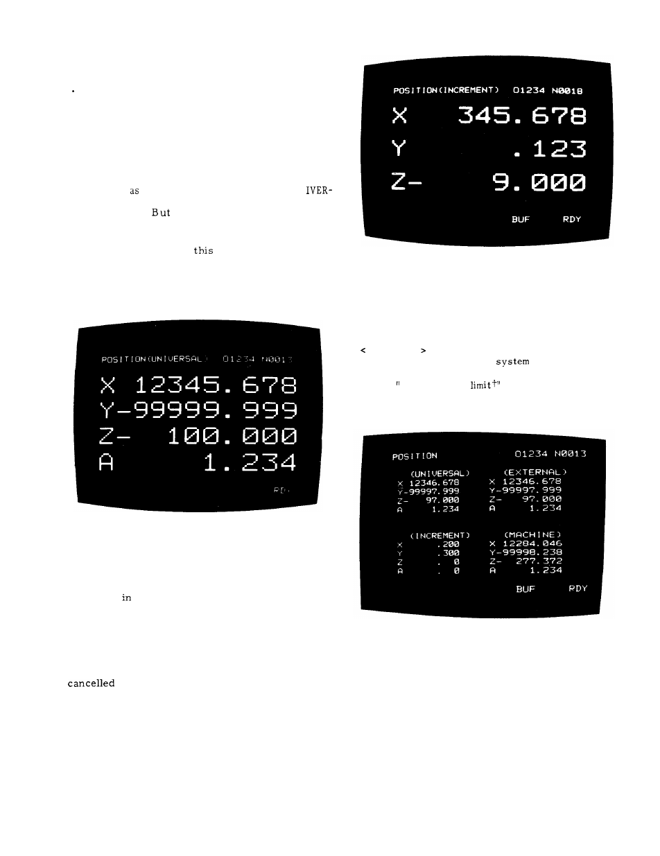
4 . 3 . 4 . 3 C U R R E N T P O S I T I O N D I S P L A Y ( I N -
CREMENT) :
P O S I T I O N [ I N C R E M E N T I
Displayed
this mode are:
. In automatic mode, distance to the end point of
the block at every moment
. In manual mode, distance to the position where
manual operation is to start.
The increment display in manual mode will be
in automatic mode.
(Fig. 4.21)
Fig. 4.21 Current Position Display
(Increment) - Example
4. 3.4.4 CURRENT POSITION DISPLAY (ALL) :
P O S I T I O N
. All position data will be displayed.
MACHINE coordinates indicate the current
position in the coordinate
whose origin
is the reference point set up by resetting.
Data for stored
stroke
and “pitch error
compensation” functions are defined in this
coordinate system .
(Fig. 4.22)
Fig. 4.22 Current Position Display
( All) - Example
4. 3.4.5 SERVO POSITIONING ERROR DISPLAY:
ERROR PULSE
This
mode will be normally used during
maintenance.
Servo positioning error means
the
difference
between the command position and the current
tool position.
Error will be displayed in units
of pulse.
144