Yaskawa J50M Instructions User Manual
Page 205
3.
4.
5.
6.
7.
8.
9.
switch movable section by hand (l-layer snap action
is provided).
Then the power supply can be turned on with the
door open.
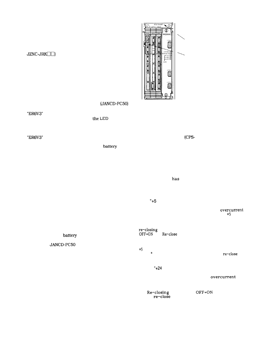
Open the door so that the CPU module (model :
mounted inside of the front door can
be seen.
Note :
Some models have the CPU module mounted
not on the door but on the main unit.
Depress POWER ON pushbutton. Where the control
is equipped with a door interlock switch, pull it out
by hand. The power can be turned on, with the door
open.
Verify that LED1 on the CPU module
lights, which indicates that replacement of battery
is needed.
Fig. 7.2 shows the positions of
indicator
lamp and the battery.
Check for the defective battery by the above
procedure.
: YE modelJANCD-BB51
Turn off the power supply. Remove the
cover
to remove the existing battery mounted on the holder.
Insert new battery into the battery holder and then
plug it into the connector.
Note :
The connector may be inserted even upside
down.
When door interlock switch is provided, depress the
movable section.
The switch returns to the previous position and the
power supply cannot be turned on when the door is
“open”.
Be sure to close the front door.
10. Turn the power off.
11. Confirm that the
alarm display on the CRT
screen of NC operation panel and red display lamp on
the front of
board have been turned off.
Notes :
(1) Since the work is performed with the front
door open, it is necessary to work as quickly as
possible (to prevent contamination by oil mist,
dust, etc. ).
(2) Contamination by water oil, dirt, etc. to
printed boards, connectors, cables, etc. inside
the equipment must be avoided.
BATTERY FOR NC MEMORY
BATTERY ALARM INDICATOR
LAMP FOR NC MEMORY
Fig. 7.2
7.3
POWER SUPPLY
Various kinds of protective functions are provided for
compound power supply
18 F).
However, in the event of a malfunction such as no power
to NC, it is necessary to confirm the items stated below,
immediately alert maintenance personnel and then
rectify the causes.
7.3.1
“SOURCE” LED [GREEN] UNLIT
(1)
Check if the main breaker of power supply
has tripped or
an open phase.
(2) Check if the compound control power supply
is properly operating.
7.3.2
V“ LED (RED) LIT
(1)
The red LED lights up when an
due to the short-circuit of output from V or
an overvoltage of +5 V is detected.
(2) If the trouble occurs due to overcurrent,
is possible by means of POWER
.
after removing the cause of
trouble.
(3) If the trouble is caused by the overvoltage of
V, turn off the main breaker once, confirm
that SOURCE” LED is out, and then
the
main breaker.
7.3.3
V
LED (RED) LIT
(1)
This red LED is lit when an
due
to the short-circuit of output from +24 V is
detected.
(2)
by POWER
is possible,
Thus,
after removing the cause.
197