Yaskawa J50M Instructions User Manual
Page 16
2.3.4.2 LINEAR AXIS (U, V OR W AXIS) (Cent’d)
The unit output increment and input increment for
C-axis is the same as the other linear axes, X, Y
and Z.
No discrimination is necessary.
When inch system is selected by parameter, input
values must be in inches for C–axis.
Y
v
B
—
u
-
x
c
A
z
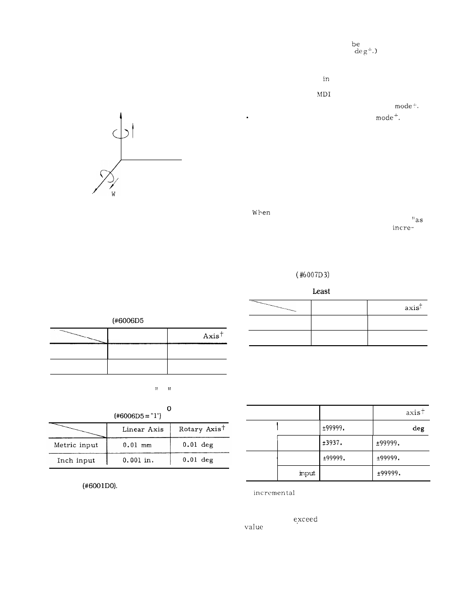
Fig. 2.1 4th Axis in Right-hand
Coordinate System
2.3.5
LEAST INPUT INCREMENT AND LEAST OUTPUT
INCREMENT
2.3.5.1 LEAST INPUT INCREMENT
The minimum input units that can be commanded
by punched tape or MDI are shown in Table
2.9.
Table 2.9 Least Input Increment
= “O’)
Linear Axis
R o t a r y
Metric input
O. 001 mm
0.001 deg
Inch input
0.0001 in
O. 001 deg
Least input increment times ten can be set by
setting parameter #6006D5 at 1.
Input Increment X 1
Note : Selection of metric system or inch system is made
by setting
Tool offset value must always
written in O. 001
mm (or 0.0001 inch, or 0.001
, and offset
is possible in these units.
In 0.01 mm increment system, the following op-
eration must be made
the unit of O. 01 mm.
. Write operation in
mode .
. Programming for operation in MEMORY
Program editing operation in EDT
Notes :
If NC programs set by O. 001 mm is fed in-
to or stored in an equipment set by 0.01 mm
increment, the machine will move ten times
the intended dimensions.
If the increment system is switched when the
contents of NC tape are stored in memory, the
machine will move by ten times or one tenth of
the commanded dimensions .
the stored program is punched out on the
tape-’ ,
the stored figures are punched out
stored” regardless of switching of the
ment system.
2.3.5.2 LEAST OUTPUT INCREMENT
Least output increment is the minimum unit of tool
motion.
Selection of metric or inch output is made
by parameter
setting.
Table 2.10
Output Increment
Linear axis
R o t a r y
Metric output
0.001 mm
0.001 deg
Inch output
0.0001 in.
0.001 deg
2.3.6
MAXIMUM PROGRAMMABLE DIMENSIONS
Maximum programmable dimensions of move com-
mand are shown below.
Table 2.11 Maximum Programmable Dimensions
Linear axis
Rotary
!
Metric input
999 mm
*99999.999
Metric
output
Inch input
0078 in.
999 deg
Inch
Metric input
999 mm
999 deg
output
Inch
*9999.9999 in.
999 deg
In
programming , input values must
not exceed the maximum programmable value.
In absolute programming , move amount of each
axis must not
the maximum programmable
8