Yaskawa J50M Instructions User Manual
Page 53
Y.
Cautions and remarks tool
compen-
sation C
A .
Maximum programmable dimensions (Refer to
Table 2. 14) is not changed even in tool
radius compensation C.
B.
Programmed shapes that produce input
errors
Input error “ 045” occurs with the follow-
ing programmed shapes.
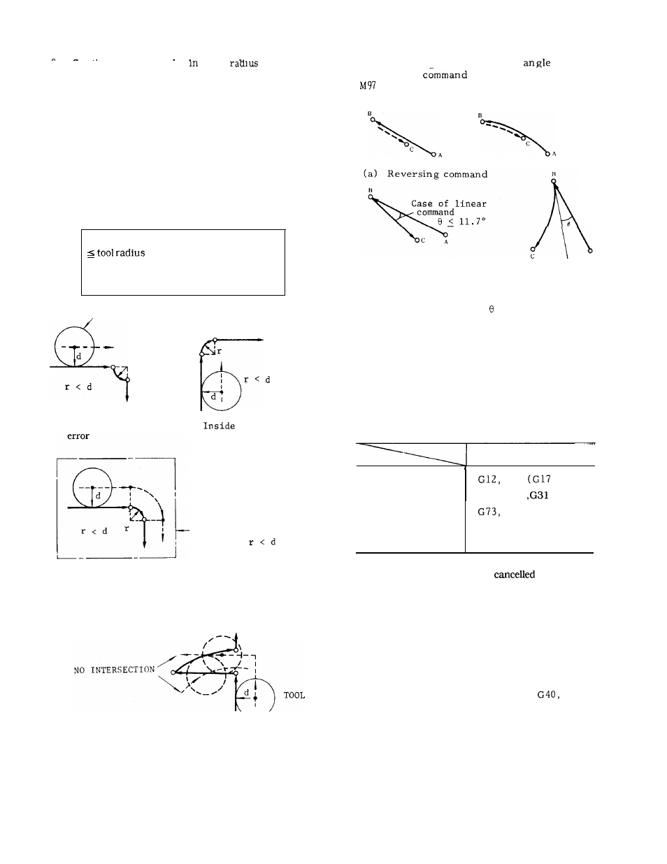
(1) When programming an inside arc with tool
(3) When reversing command or an
close
to reversing
is programmed
i n
(Outside Corner Circular Arc Point
Off)
mode.
compensation, if
Programmed arc radius r + 5 (setting unit)
d
5: 0.001 (in mm)
: 0.0001 (in inches)
TOOL
d
‘r
(a) Outside compensation
(b)
c o m p e n s a t i o n
(b) Command close
Note:
With the
to reversing
circular arc com-
mand,
tangent angle
a l o n e i s i n s u f f i -
c i e n t .
Fig. 2.48
In M96 mode, all of the above shapes are
correctly compensated.
c.
Input errors occur when the following G codes
are programmed in compensation mode.
e r r o r
Prohibited G codes
G codes causing
G13
to G19)
input errors
G28, G29
Outside compensation
is correctly made
even when
Fig. 2.46
(2) When
no
intersection point exists
locus of the offset tool center.
on the
N o – i n t e r s e c t i o n
error occurs when
tool
radius is too
large relative to
the programmed shape.
Fig. 2.47
D,
E.
G74, G76, G77
G81 to G 8 9
G92
* If a “reset operation” is performed in compensa-
tion mode, compensation is
and G40
remains.
Tool radius compensation C is applied to
the movement path offset by tool length
offset and tool position offset.
H o w e v e r ,
in principle, avoid applying compensation
C to the path using tool position offset
for compensation of tool radius.
When programming G41, G42 and
GOO
or GO1 and an F code should be program-
med in the same block or in a preceding
block.
45