Yaskawa J50M Instructions User Manual
Page 182
5.2 OPERATION PROCEDURE
5.2.1.1
With this function, the tool is returned to the
reference point manually. The procedure is as
follows .
2.
3.
4.
5.
Set the mode select switch to RAPID or JOG.
Manually move the tool to a position some
distance away from the reference point.
When the tool is within the range A shown
below, it can be brought back to the refer-
ence point in the normal way, as described
below.
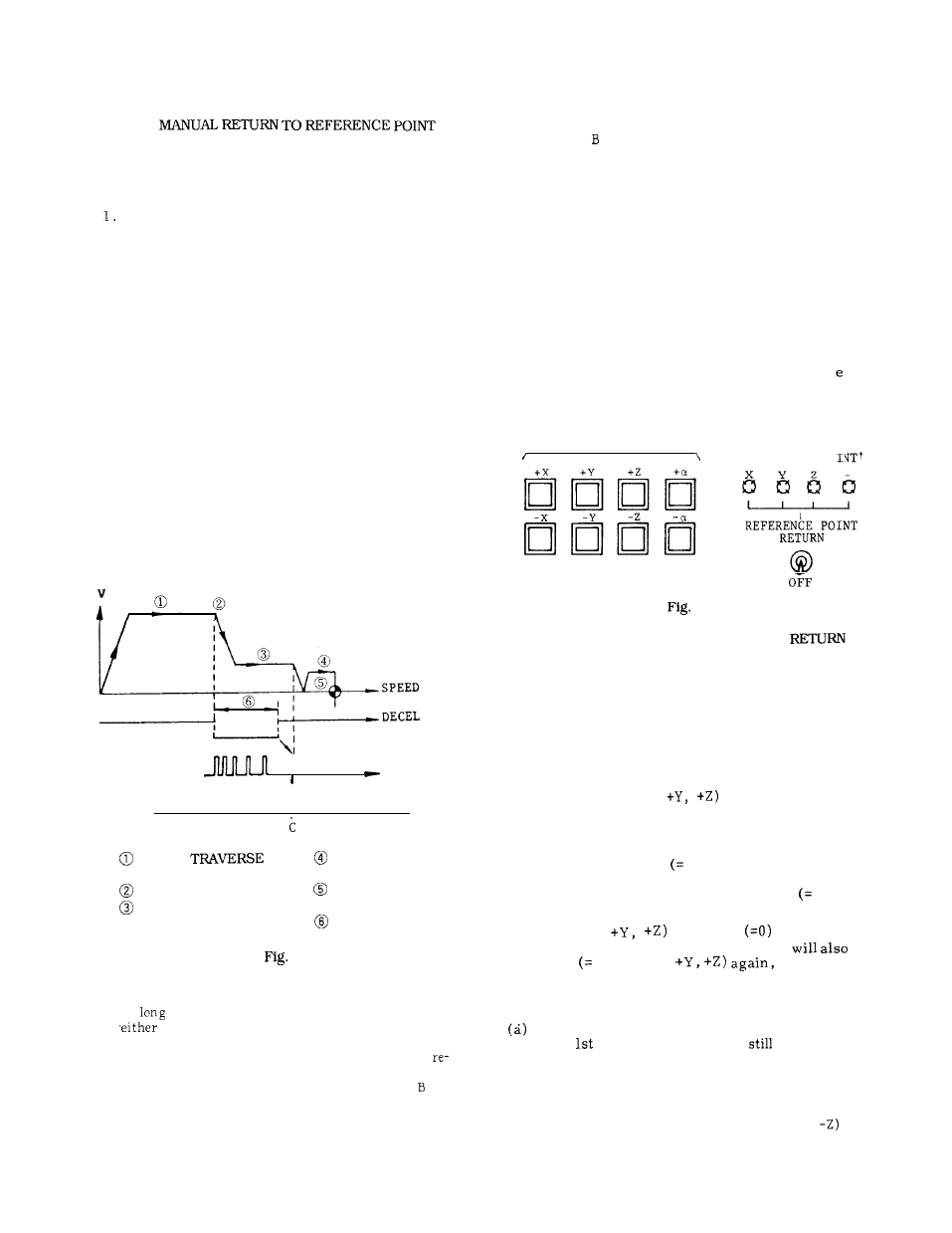
Turn on the REFERENCE POINT RETURN
switch.
Keep the JOG button for the return direction
depressed.
The tool starts to move as in the
normal manual control, but the speed is de-
celerated at the deceleration point, and the
motion stops automatically at the reference
point.
Then, the reference point lamp for the relevant axis
lights at reference point return completion.
SEQUENCE
LS SIGNAL
R E F E R E N C E
- - - -
POINT
S I G N A L
AREA A
1
1
AREA B
RAPID
RATE
(#6280 - #6283)
DECELERATION POINT
APPROACH SPEED 1
(#6310 - #6313)
5.24
Notes :
APPROACH SPEED 2
(#6316 - #6319)
TRAVERSE DISTANCE
(#6304 - #6307)
DOG WIDTH
a.
As
as the power supply is turned on ,
the manual or the automatic return to
reference point can be initiated, regardless
of the tool position , but the tool will not
turn to the reference point accurately if the
tool is started from a point in the area . Be
sure to bring the tool into the area A before
initiating a manual or automatic return motion.
b.
c.
d.
e.
Once
the tool is returned to the reference
point, the point C is stored, and if the refer-
ence return motion is initiated from a point in
the area , this is regarded as an error. Start
the reference return motion from a position in
the area A.
Once the tool is returned to the reference
point, it can not be further moved in the same
direction unless the REFERENCE POINT RE-
TURN switch is turned off.
While the MACHINE LOCK switch is on , the
reference point return function is ineffective.
Do not return the tool to the reference point
by the manual reference point return func-
tion, while the buffer is loaded with blocks
read in advance of execution, because th
stored motion data will be erased by the
reference point return motion.
JOG
REFERENCE PO
5.25
5.2.1.2 2ND MANUAL REFERENCE POINT
This function is used to automatically position the
machine at the 2nd reference point under manual
mode.
Positioning can be made without observing
upon which side of the 2nd zero point the current
position is located.
(1) Function
(a) Command ZRN2 (2nd reference point return
request) and +X (or
under JOG or RAPID
mode, to position the X-axis (or Y-axis,
Z-axis) at
the 2nd reference point.
The move speed for
positioning is the JOG or RAPID feedrate.
(b) If ZRN2 turns off
O) while moving to the
2nd reference point, the move will stop before
completion.
If the ZRN2 is turned on
1) again,
the move will restart.
(c) If +X (or
turns off
while moving
to the 2nd reference point, the move
stop.
T u r n o n
1) +X (or
to restart the
move.
(2) Notes
Inputting the 2nd reference point return
m o d e
when the
reference point is
not completed
is not permitted.
(b) The -X (or -Y, -Z) inputs are also valid in the
2nd reference point return mode. Therefore, the
2nd reference point return will not stop before
completion by turning on the -X (or -y,
input.
174