Appendix-3 stored leadscrew error compensation, Cent’d) – Yaskawa J50M Instructions User Manual
Page 250
APPENDIX-3 STORED LEADSCREW ERROR COMPENSATION
(Cent’d)
To use the 4th-axis as the rotary axis, follow the rules
REFERENCE
shown below in addition to the rules for setting X-, Y-,
CORRECTION NO.
and Z-axes.
CORRECTING
/
AND
PoINT
0, (1)
POINT
(1) Compensation Interval
The compensation interval should be more than
10000 pulses and the quotient obtained by
dividing 360000 by the compensation interval
become a positive integer.
(2) Compensation Amount at Reference Point
6,
The compensation amount to be set to the refer-
ence point should be as follows :
a.
Absolute setting . . . “O”
b. Incremental setting . . . “ O“
5, (1)
In the case of incremental setting, set such a
(1)
value for the compensation amount at compen-
sation maximum point that
the sum of the
-
COMPENSATION AMOUNT
pensation amount of each point becomes “O. “
FOR INCREMENTAL
SETTING
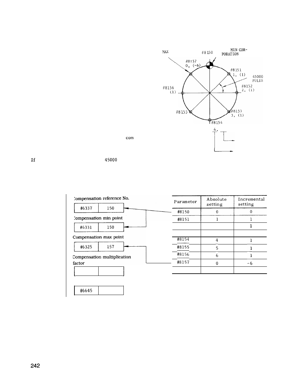
(3) Sample Writing
the compensation interval is
pulses (one
rotation divided by 8) as shown below, set the
parameters as follows.
4th axis of
rotary axis
COMPENSATION
FOR ABSOLUTE
AMOUNT
Compensation parameter at
each point
Compensation reference No.
#6337
150
Compensation min point
#6331
150
#8152
2
#8153
3
1
Compensation max point
Compensation multiplication
#6071
1
Compensation point
45000