Yaskawa J50M Instructions User Manual
Page 110
2.11.5 VARIABLES (Cent’d)
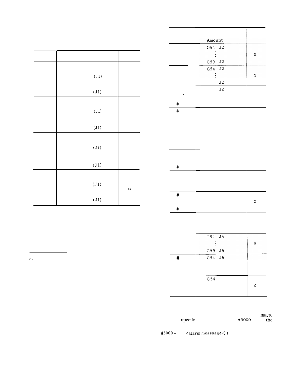
Table 2.36 System Variables and Work
Coordinate System Shift Amount
System
Variable
#2500
#2501
#2506
#2600
#2601
#2606
#2700
#2701
#2706
#2800
#2801
#2806
Work Coordinate
System Shift Amount
External work coordinate
system correction amount
G54
G59
External work coordinate
system correction amount
G54
G59
External work coordinate
system correction amount
G54
G59
External work coordinate
system correction amount
G54
G59
pindle
System
Variables
# 2511
.
# 2516
x
# 2611
# 2616
Y
# 2711
2716
2521
.
# 2526
# 2621
# 2626
z
# 2721
2726
# 2531
# 2536
Note : When “work coordinate system setting B“ feature is
provided, system variables listed in Table on page 105
can be applied.
(d) When one of the above system variables is
specified to the left-hand of an operational ex-
pression, its value can be changed.
Sample Programs
#116 = #2016 ;
The contents of tool offset number 16 are
substituted
for common variable #116.
b.
#2506
❑
#4 ;
The work coordinate system shift amount of
G59 X-axis is erased and the contents of
local variable #4 are set.
2631
2636
# 2731
# 2736
# 2541
# 2546
2641
# 2646
# 2741
# 2746
Work coordinate
System Shift
A x i s
x
Y
G 5 9
G 5 4
z
G59 J2
G54 J3
x
G59 J3
G54 J3
Y
G59 J3
G54 J3
z
G59 J3
G 5 4 J 4
x
G59 J4
G54 J4
G59 J4
G54 J4
z
.
G59 J4
G54 J5
G59 J5
J 5
G59 J5
Y
D.
Alarm Message Display (#3000)
When a condition to be alarmed occurs in a user
program,
the system variable
to put
machine in the alarm state.
n (
102