Yaskawa J50M Instructions User Manual
Page 130
2.12.2.5
P R E C A U T I O N S ( C e n t ’ d )
R e s t a r t
cannot
executed for program restart
to the block during solid tap mode.
G93 has
to be modified by
and be executed.
2.12.3
SOLID TAP RELATED FUNCTION
The following functions are added or modified
the optional addition of solid tap function.
(1) Servo Positioning Error Display
In the solid tap
mode, servo positioning error of
the spindle is displayed at X-axis and the number
synchronous error pulses of the spindle and
Z - a x i s i s d i s p l a y e d a t Y - a x i s , r e s p e c t i v e l y , o f
servo positioning error display screen.
( Z - a x i s
displays servo positioning error of Z-axis. )
However,
pulse display at Y-axis is not precise in
continuous mode (single block OFF) .
I f p a r a m e t e r # 6 0 6 5
is 1, peak value of
synchronous error pulses can be displayed at
X- and
(X-axis : Plus peak value,
z-axis : Minus peak value)
(2) Error Detect in Solid Tap
R a p i d t r a v e r s e c o m m a n d i n s o l i d t a p ( X , Y
positioning, Z-axis positioning) can be made to
Error Detect OFF mode by setting parameter #6065
DO
to 1.
Cycle time can be shortened by turning this
parameter ON.
Be careful of the program, since
it proceeds to Z-axis block just after completing
pulse distribution for positioning X and Y.
(3) Alarm Code
The following alarm codes are added.
Alarm 090
ERROR
)
( C o n t e n t s ) .
There is a command other than
G93, S, F and N in G93 block.
G code at 01 group is other
than 00 or 01 when G93 is
specified.,
G code that should not be
specified was specified in G93
mode.
Pitch F of solid tap is beyond
the allowable range
(200 mm/rev.).
Alarm 091 (TAP ERROR)
(Contents)
. When solid tap is executed,
p o s i t i o n c o n t r o l l o o p i s n o t
formed to the spindle.
. SLPC turned OFF before com-
pleting index
at the time of
indexing with G93.
Higher return speed function upon solid tap
The return solid tap cutting feedrate (cutting
from Z point
R point) can be controlled at
n times (O. 1 n 25. 5) the forward speed
(cutting from R point
Z point) , by setting
parameter #6470.
Note that the commanded S
x
magnification
of the spindle speed is clamped at the maximum
solid tap speed of #6471.
When #6470 = O, it is regarded as n = 1.
#6470
Specification range O to 255
Unit 1 = 0.1 times
When O is specified, the magnification is 1
time.
2.12.4 SOLID TAP
AND ITS RELATION WITH
SPINDLE CONTROL
(1) 1/0 Used for Solid Tap
a.
OUT Signal
G93M Output (#12070): G93 Solid Tap Mode
Output Signal
The signal is output when G93 is specified.
The machine side receives this signal, turns
ON the spindle forward signal and returns
SLPC ( spindle loop command input signal)
after confirming the spindle zero speed.
Notes :
the soft start function at the same time SLPC
turns on, if the spindle is equipped with soft start
circuit (so that NC unit can control
Turn off the spindIe reverse input
gear
shifting input
and spindle orientation input
SLPS Output (#12071): Spindle Loop Status
Output Signal
The signal is output at the time when NC
forms position control loop to the spindle for
solid tap.
G93 block ends at the time this
signal is output.
IN Signal
SLPC Input (#13133):
Spindle Loop Command
Input Signal
The signal is to form the spindle position
control signal to the NC unit.
The NC unit returns SLPS by forming the
position control loop to the spindle after
ensuring
t h e s p i n d l e s t o p ( f o l l o w i n g t h e
number of revolutions at #6473) when this
input turns ON.
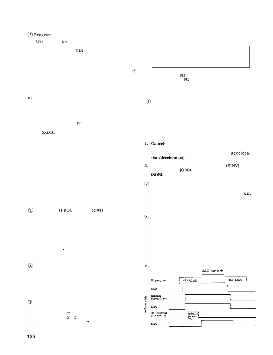
Time Chart
I
G93
—
—
,
1