Part program tape coding, 1 tape code – Yaskawa J50M Instructions User Manual
Page 138
2.14.3 CIRCULAR PROJECTION COMPENSATION
(Cent’d)
(3) Adjustment
The following are standard setting and adjustment
procedures.
‘
2
EXAMPLE
G92 XO YO ZO
G91
F3000
G198 Y25.
G03 I-25.
GO1 G199 Y25.
(a) Adjustment procedure
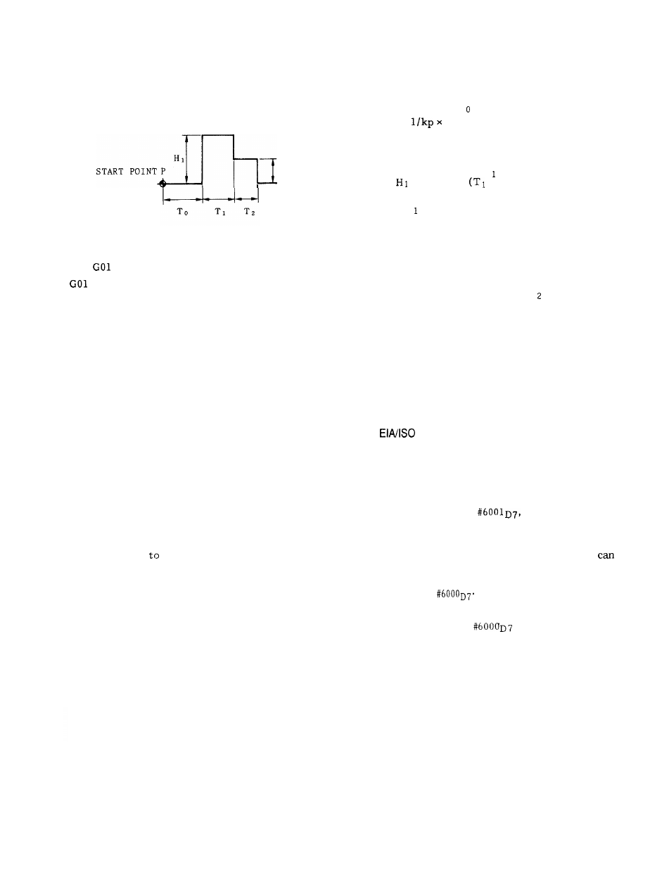
(i) The start point P is fixed at the position where
the sign of the (segment) changes.
(ii) The delay time T is calculated as follows.
To =
0 . 7 [ s ]
(Half of the above value is set in the
parameter, as 1 = 2 ms. )
(iii) Increase the height H from the temporary
setting
= 20 by 5
= 10 when H
2
= O, T
2
=
O) , and observe the effect.
(iv) Feed H while checking the effect by actual
cutting, orbit analyzer, plan, DBB, etc.
(b) Notes
(i) Set the soft hammer parameter after setting the
form compensation parameter.
(ii) If normal adjustment is not effective enough,
try adjustment by changing To , H and T
2
.
GOO Y-50.
M30
3. PART PROGRAM TAPE CODING
3.1 TAPE CODE
3.1.2
AUTO-SELECT
3.1.1 TAPE CODE
With this control, both the EIA and the 1S0 codes
can be used.
EIA code:
EIA RS-244-A
ISO code: 1S0 84
Table 3.1 shows the EIA and 1S0 pnched tape formats.
Before starting
program any machining oper-
ation,
a decision must be made as to the code to
be used.
Before starting to use part program tapes, the
control must be switched to the same code as the
tapes, inaccordance with the procedure for writ-
ing-setting under 4.3.6, “ DISPLAY AND WRITING
OF SETTING DATA .“
Despite the content of
the control
is automatically adapted to the code used for the
part program tape.
The control recognizes the
code used when it reads the first EOB code in the
label skip mode, and all the subsequent data
be read automatically in that code.
For
punching tapes, the code must be selected by
the setting of
When “O” is set with #6000D7 .0. EIA code
When “l” is set with
. . . 1S0 code
130