Yaskawa J50M Instructions User Manual
Page 70
2.9.24 WORK COORDINATE SYSTEM SETTING B
(G52 TO G59) (Cent’d)
Pm . . . . . selects commands from G54 to
= G54
to to
= G59
Jn . . . . .
selects any of
to J5.
Example:
. . . . G55J3
. . . . .
(b) Omission of J or specification of JO will be
considered equivalent to
(c) Error
occur if a wrong numerical
value is specified for m or n.
(d)
will occur if the 4th axis is commanded
when executing commands J2 to J5.
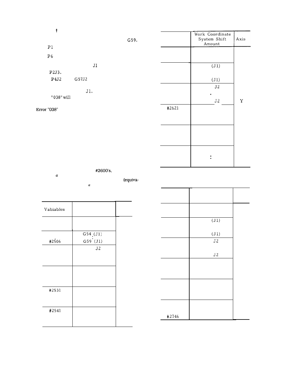
(9) Work coordinate system shifting in user macro
(a) The amount of work coordinate shifting (and
external work coordinate system corrections) can
be read by using a system variable for the right
element of an arithmetic expression.
(b) The values can be changed by using the
above system variable as the left element.
(c) The correspondence between the system variable and
the amount of work coordinate shift will appear as listed
in the following table.
Y-axis of
the Z-axis of
#2700’s the axes of #2800’s have the same corre-
spondence as the X-axis. Command G54 to G59
Table 2.26 (b)
System
Variables
External work
coordinate system
correction amount
#2600
#2601
G54
#2606
G59
#2611
G54
#2616
G59
G54 J3
G 5 9 J 3
#2626
#2631
G54 J4
#2636
G54 J5
#2641
G54 J5
#2646
G59 J5
Table 2.26 (c)
lent to J 1) only in the case of axis.
Work Coordinate
System
Variables
Shift Amount
System
External work
coordinate system
correction amount
G54
G59
G 5 4
G 5 9
G 5 4 J 3
G 5 9 J 3
Axis
z
Table 2.26 (a)
System
Work Coordinate
System Shift
Amount
Axis
x
#2700
External work
#2500
coordinate system
correction amount
#2701
#2501
#2706
G 5 4
#2711
#2716
#2511
#2516
#2521
#2721
G 5 9 J 2
G 5 4 J 3
#2726
G 5 4 J 4
G 5 9 J 4
#2526
G 5 9 J 3
#2731
#2736
G 5 4 J 4
#2536
G54 J5
.
G 5 9 J 5
G 5 4 J 4
#2741
G 5 4 J 5
G 5 9 J 5
#2546
62