Yaskawa J50M Instructions User Manual
Page 236
PARAMETER NUMBERS AND THEIR CONTENTS
(Cent’d)
#6274:
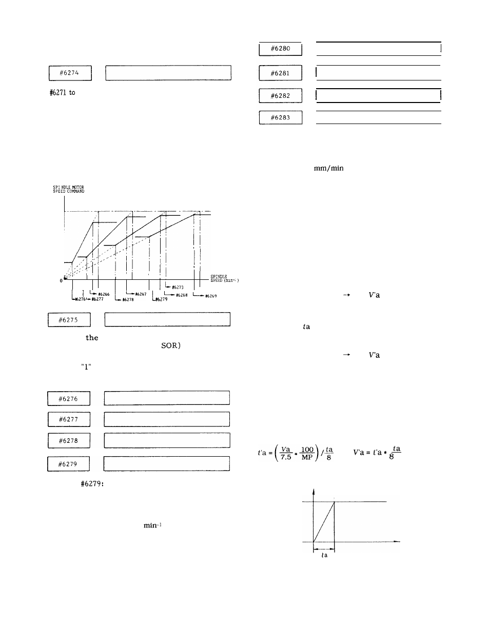
Specifies the maximum speed of the spindle D/A
(10 V/4095), respectively, for gears 1, 2, 3 and 4 each
selected by an input signal (specifiable in S5-digit
designation). Set the spindle speed applicable when
the speed command voltage is 10 V.
Setting :
“l” = 1 rein-l or 10 rein-l
(Set by parameter #6022 D7)
Setting range : 1 to 32767
‘
0
”
I
I
- #627 1
#6272
- #6274
Specifies
spindle motor speed in effect
when a spindle orientation (
input is
entered (specifiable in S5-digit designation).
Setting :
= 1 rein-l
Setting range : 1 to 32767
#6276 to
Specifies the minimum speed of the spindle, respec-
tively, for gears 1, 2, 3 and 4 each selected by an
input signal (specifiable in S5-digit designation).
Setting : “l” = 1 rein-l or 10
(Set by parameter #6022 D7)
Setting range : 0 to 32767
I
X-axis
Y – a x i s
Z–axis
I
4th axis
#6280 to #6283 :
Specifies the rapid traverse rate, respectively, on the
X-, Y-, Z- and 4th-axes.
Setting : “l” = 1
or 0.1 inch/rein
Setting range : 0 to 30000
Note :
Be sure to turn the power on and off after
changing the parameter.
(Reference)
The following calculations are made between rapid
traverse rate and acceleration and deceleration for re-
computing the rapid traverse rate and second-stage
time constant switching rate. The example of calcula-
tions shown below is made for the parameters related
to X-axis, but the same can be applied also to Y-axis,
Z-axis or 4th-axis.
Rapid traverse rate :
Va = #6280
Rate
recreated by the
calculations.
Acceleration/deceleration 1st-stage time constant :
= #6286
2nd-stage time constant switching rate :
Vb = #6292
Rate
recreated by the
calculations.
Acceleration/deceleration 2nd-step time constant :
#6298
(a) Where 2nd-step acceleration and deceleration are
not used :
Condition : Vb = O
t b = O
* 7 . 5
RATE
Va
TIME
228