Yaskawa J50M Instructions User Manual
Page 239
. Reference point return direction:
#6010
D3
Reference point return enabled/disabled:
#6016
X-ax is
Y-axis
Z–axis
4th axis
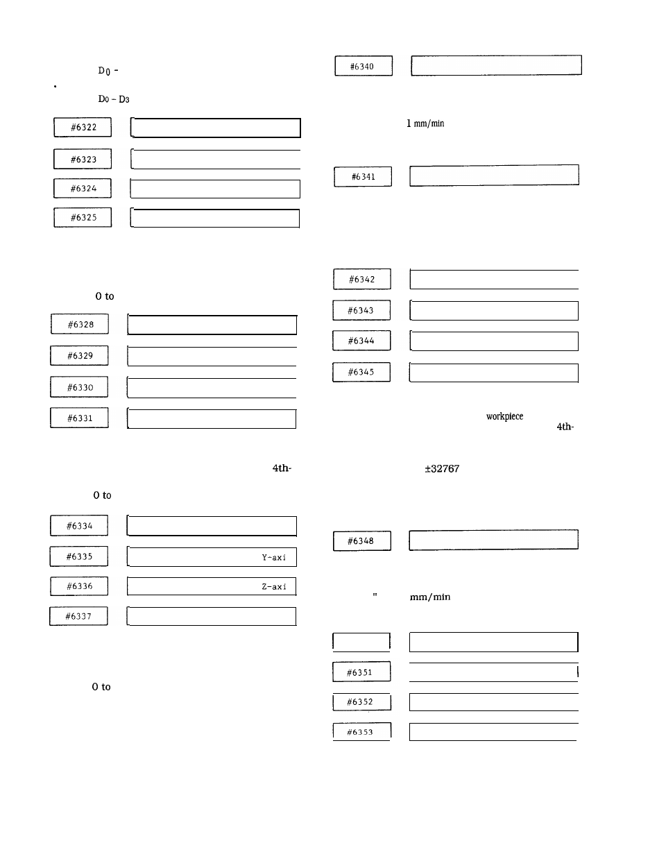
#6322 to #6325 :
Specifies the number of the end point for pitch error
compensation, respectively, onthe X-, Y-,
Z-
and 4th-
axes.
Setting :
511
X-axis
Y-axis
Z – a x i s
4 t h a x i s
#6328 to #6331 :
Specifies the number of the start point for pitch error
compensation, respectively, on the X-, Y-, Z- and
axes.
Setting :
511
X–axis
s
s
4th axis
#6334 to #6337 :
Specifies the reference point for pitch error compen-
sation, respectively, on the X-, Y-, Z- and 4th-axes.
Setting :
511
Specifies the external deceleration speed for
rapid traverse.
Setting : “l” =
or 0.1 inch/rein
(common to all axes)
Setting range : 0 to 30000
Specifies the external deceleration speed for
cutting feed.
Setting : “ 1“ = 1 mm/min (common to all axes)
Setting range : 0
to
30000
X – a x i s
Y - a x i s
Z-axis
4th axis
#6342 to #6345 :
Specifies the offset in external
coordinate
system shift, respectively,
on the X-, Y-, Z- and
axes.
Setting : “l” = 0.001 mm
Setting range : 0 to
Note :
Usually, these parameters are
automatically set from the machine tool side
through the external data input function.
Specifies the maximum speed for handle feed on
the rotary axes (A, B, C) .
Setting : 1“ =
Setting range :
#6350
1
or 0.1 inch/rein
O to 24000
X–axis
I
Y - a x i s
Z-axis
I
4th
axis
231