Yaskawa J50M Instructions User Manual
Page 183

(c) If the mode
is switched to modes other than the
JOG or RAPID
modes during the 2nd reference
point return, the ZRN2 input is regarded to be
turned off.
(d) The 1st reference point return mode and the
2nd reference point return mode cannot be used at
the same time.
If the two inputs are turned on at
the same time, both modes will become invalid.
( e ) T h e - X ( o r - Y ,
-Z) input as well
the +X (or
,
input is effective as the 2nd reference
point return input.
5.2.1.3 EASY REFERENCE POINT RETURN t
When setting the machine reference point the
position where the C-phase pulse is actually output
to the dog position cannot be measured.
Thus the
dog position must be adjusted and tried several
times to find the optimum position.
This function
eliminates the need of the uncertain dog adjustment;
the optimum reference point position can be set
rapidly and without failure, just by rewriting the
internal data.
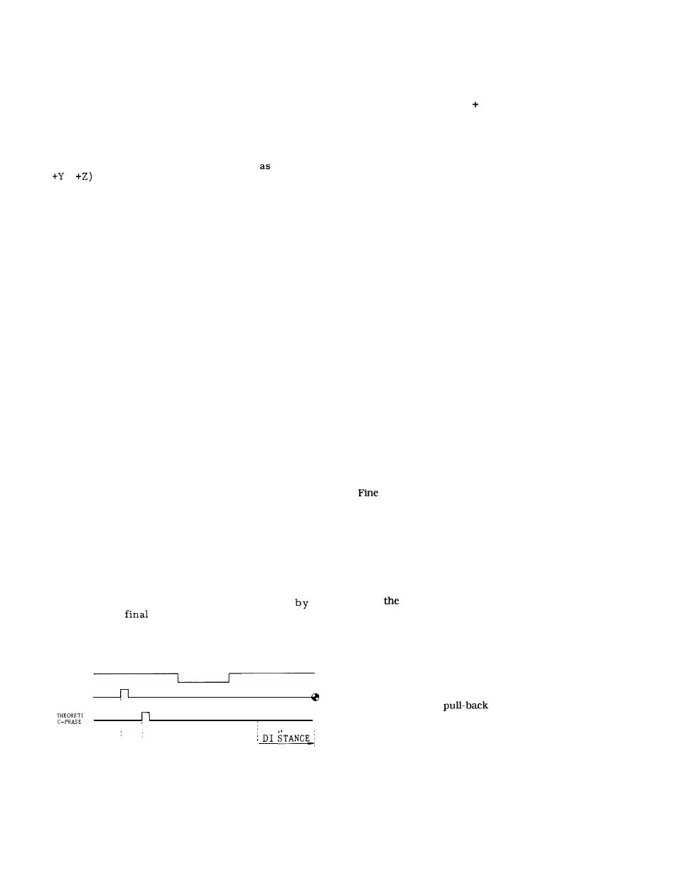
The new concept of the theoretical C-phase
pulse is employed to embody this function. The
C-phase pulse position output for a single pulse per
motor rotation is mechanically fixed, and cannot be
adjusted.
T h e r e f o r e ,
another theoretical C–phase
pulse that generates at an optional position of a
motor rotation is assumed. This theoretical C-phase
pulse is represented by the shift distance from the
C-phase pulse.
(1) Function
The reference point return operation in this
function is completely the same as the conventional
reference point return.
The concept of a
theoretical C-phase is used in this function to allow
the positional relation between the dog and the
C-phase pulse as well as the relation between the
dog and the reference point position to be changed,
can be accomplished just by rewriting the
parameter, instead of adjusting the dog position.
Therefore, latch mistakes can be avoided, even
when the C-phase pulse is near the dog switching
point, by increasing or decreasing the theoretical
C-phase shift distance.
The distance from the dog
to the reference point can be kept constant,
adjusting the
run distance.
In other words,
the reference point position can be set at an
optional distance from the dog, regardless of the
C–phase pulse position.
‘
O G
C-PHASE
n
n
n
CAL
I-1
n
I
RUN
e
SHIFT DISTANCE
REFERENCE POINT
Fig. 5.26
(2) Related parameters
#6010 DO to D3 :
#6016 DO to D3 :
#6304 to #6307 :
#6310 to #6313 :
#6316 to #6319 :
#6444 to #6447 :
#6480 to #6483 :
Note :
Reference point return direction of each
axis
1 : -/0 :
Reference point return of each axis
1: Enabled/O : Disabled
Run distance from the theoretical
C-phase
Setting range : -32768 to 32767
Reference point return approach speed 1
Setting range : 0 to 24000
Reference point return approach speed 2
Setting range : 0 to 24000
Move distance per motor rotation
Setting range : 1 to 65535
Theoretical C-phase shift distance
Setting range : -32768 to 32767
Always turn off the power one time when change is
made to the above parameters.
(3) Adjustment
(a) When the deceleration limit switch of the
machine reference point is at an optional position
( i ) Set the parameter. The temporary setting is run dis-
tance (#6304 to #6307) O, theoretical C-phase shift dis-
tance (#6480 to #6483) 1000.
(ii ) Perform reference point return.
(iii) If it stopped before the machine reference point, add
the distance from that position to the machine reference
point to the theoretical C-phase shift distance.
If it stopped beyond the machine reference point, subtract
the distance from that position to the machine reference
point from the theoretical C-phase shift distance.
(iv)
adjustment for the true machine reference point
can be made by the theoretical C-phase shift distance or
by the run distance.
(b) When the machine reference point and the decelera-
tion limit switch are at 1/2 the distance of the ball screw
pitch.
(i) Adjust the machine reference point assuming that the
above machine reference point (iii) is at 1/2 the ball screw
pitch. Fine adjustment for the true machine point can be
made by
run distance.
(4) Notes
(a) Perform reference point return after returning from
the deceleration limit switch position. If the distance to
go beyond the deceleration limit switch is too short,
alarms 231 to 234 occur.
(b) If the setting of the theoretical C-phase shift distance
(#6480 to #6483) and the run distance (#6304 to #6307)
are not appropriate,
occurs, to cause alarms
261 to 264. If this occurs, set a larger value for the run
distance, or make any necessary parameter adjustments.
(EXAMPLE) When the theoretical C-phase shift
distance is set too large that the
distance from the deceleration limit
switch to the theoretical C-phase pulse
is larger than the motor pitch.
175