Yaskawa J50M Instructions User Manual
Page 37
The plane for making tool radius compensation by
command G41 or G42 is
determined by
G17, G18 or G19. It is not possible to designate
compensation plane including
4th axis of rotary
axis.
The
(G 17) is selected when the power is
turned on.
2.9.11
DESIGNATION BY G CODE
(G20,
Unit of input data are selectively specified by the
following G codes between metric and inch.
Metric
These G codes are programmed at the leading end
of a block of its own. If one of these G codes are
commanded, the units of all the following motions
are changed afterwards.
subsequent programs
. tool offset values
. part of setting parameters
. part of manual movements
displays
Notes :
When G20 or
is commanded, the setting of
inch/metric selection is changed. Therefore,
the state of
at the time of power
on the setting by parameter
DO. “
EXAMPLE
ER
CR
01234 ;
;
Inch input designation
. When
selection is commanded in the
program, take the following procedure before-
hand.
A. When work coordinate system ( G54 to G59)
is used, return it to base coordinate
tern.
B . Cancel all tool compensation command.
(G41 to G48)
Take the following procedure after the command
of G20
selection.
A .
Program absolute zero point
for all axes
before move command.
B .
In principle, make the display reset opera-
tion when current position display ( exter-
nal) is used.
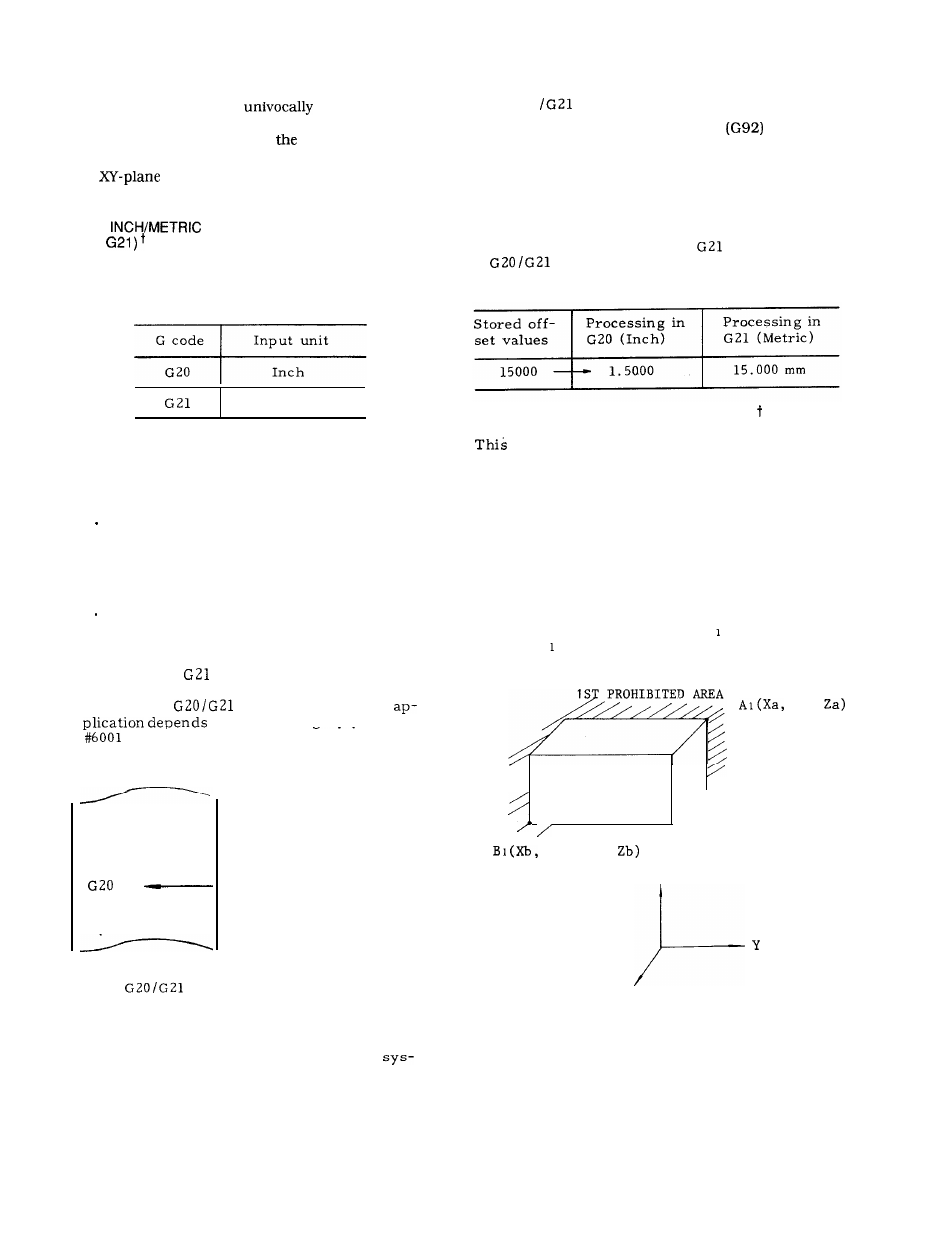
The tool offset values are processed different-
ly in the G20 mode and the
mode.
must be commanded after modifying
the tool offset values.
2.9.12 STORED STROKE LIMIT (G22, G23)
function is for checking the current tool
position during manual or automatic operation
for entry into the prohibited area specified by
parameters or by G22.
If the tool enters a pro-
hibited area, machine operation is stopped and
an. error sign is displayed.
. 1st prohibited area (stored stroke limit 1)
The area outside the area specified by a param-
eter is a prohibited area.
Generally, this can
be used as a substitute of overtravel checking
function.
Upper limit point A and lower limit
point B are specified by parameters.
/ “
/
/ ’
/ / / / / / / ’
Yb,
‘
z
Ya,
x
Fig. 2.25
29