Yaskawa J50M Instructions User Manual
Page 180
YASNAC
I
5.1.26 TOOL LENGTH MEASUREMENT PUSHBUTTON
AND
Use
the WRITE button, to automatically store
the amount of Z-axis move manually made
between
and ‘t base-position”
directly in the tool offset memory. For
operating procedure,
to 5. 2.3 Automatic
Tool Length Measurement .
TOOL
MEASURE-
WRITE &
RETRACT
Fig. 5.19
5.1.27 START LOCK SWITCH
When the START LOCK is on, CYCLE START
pushbutton does not function. Use the START
LOCK input to prevent operating the machine in
abnormal condition during automatic operation.
The input may be used as on /off switch on con-
trol station for machine.
Fig. 5.20
Note :
START LOCK
is not effective during feed
hold.
5.1.28
EDIT LOCK SWITCH
t
Turning on the EDIT LOCK switch prevents the function
of ERS, INS and ALT keys, and storing from NC tape.
When editing is made with EDIT LOCK switch turned on,
“EDIT LOCK” blinks on the CRT display.
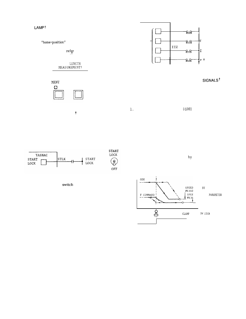
5.1.29 AXIS INTERLOCK INPUT
The control is provided with AXIS INTERLOCK
input for each axis to prevent axis motion .
Interlocking an axis in feed motion causes the
axis to slow down to a stop. When the interlock
is released, the axis motion finishes the inter-
rupted block and proceeds to the next.
AXIS
INTER
LOCK
ITX
‘x
I TY
AXIS
INTERLOCK
IT.
Fig. 5.21
5.1.30 EXTERNAL DECELERATION INPUT
In order to eliminate the danger of high speed
contact at speed end caused by erroneous motion
commands , limit switches for originating external
deceleration input signals may be installed at
selected points.
2.
During rapid traverse
and manual
operation
When the limit switch is tripped by the tool
movement, the traverse speed is decelerated
in the tripping direction to a level set by
the parameter #6340.
In the direction oppo-
site to the tripping direction, the original
speed remains unchanged.
During motion at feedrate ( G 94)
While the limit switch is being tripped, the
tool moves at a speed set
the parameter
#6341.
If the feedrate set by the F command
is lower than the rate set by the parameter,
the original feedrate remains unchanged.
v
\
\
sPEED
SET PARAMETER
‘\\
#6 340
\
SPEED SET BY
\
#6341
I
I
t ( x )
TRAVERSE RATE
LIMIT
RELEASED
OPERATED
Fig. 5.22
Interlocking one of the two or three axes being
simultaneously interpolated disables the inter-
polation
172