Yaskawa J50M Instructions User Manual
Page 137
(f)
are non-modal group G codes. Do
not use two or more G codes of the same group in
an single block.
(3) How to set the acceleration for linear
Set the maximum acceleration of a single axis in the
parameter.
Setting:
= 1/64
[
/s]
Setting example
How to accelerate to F1OOOO within
0.1 s
10/0.1 = 100
100/(60/64) = 106.7
Set 107 as the maximum acceleration parameter.
(4) How to set the form compensation parameter
Set the servo follow-up coefficient Kx, Ky . . . K4
under the form compensation mode, by the
parameter. The larger this coefficient, the better
the servo follow-up characteristics, and the better
the form precision. But, too large a setting can
cause overshoot. The following value can be
considered as guidance upon setting.
Exponential
time constant: Te (ins)
Servo follow-up coefficient:
.
[
*
1- exp
Set the above value to gain orbit precision equiv-
alent to the precision when zero is set as the
exponential
time constant.
However, the
servo delay and machine system delay cannot
completely be disregarded by this value, and the
must be adjusted while measuring the form
precision by using orbit measuring devices if the
form precision is still to be improved.
(5) Parameters related to the form compensation
function
Single-axis maximum
-#6488 (1 to 32767)
acceleration
Servo follow-up
The servo speed loop gain can be increased to
prevent the projection to some degree. However,
increasing vibration and other causes will not allow
the speed loop gain to be increased.
This function is to automatically output the
speed impulse preset as the parameter, when the
move direction of the machine changes, so that the
projection can be “hammered down. ”
(2) Parameters related to the circular projection
compensation function
(a) Circular projection compensation ON/OFF
The following parameters must be set for each axis.
x-axis :
#6056
D6
Y-axis :
#6057 D7 D6
z-axis :
#6058 D7 D6
o 0:
Circular projection compensation off
1 0:
Circular projection compensation on
Always turn the NC power off and then on when
change is made in this parameter.
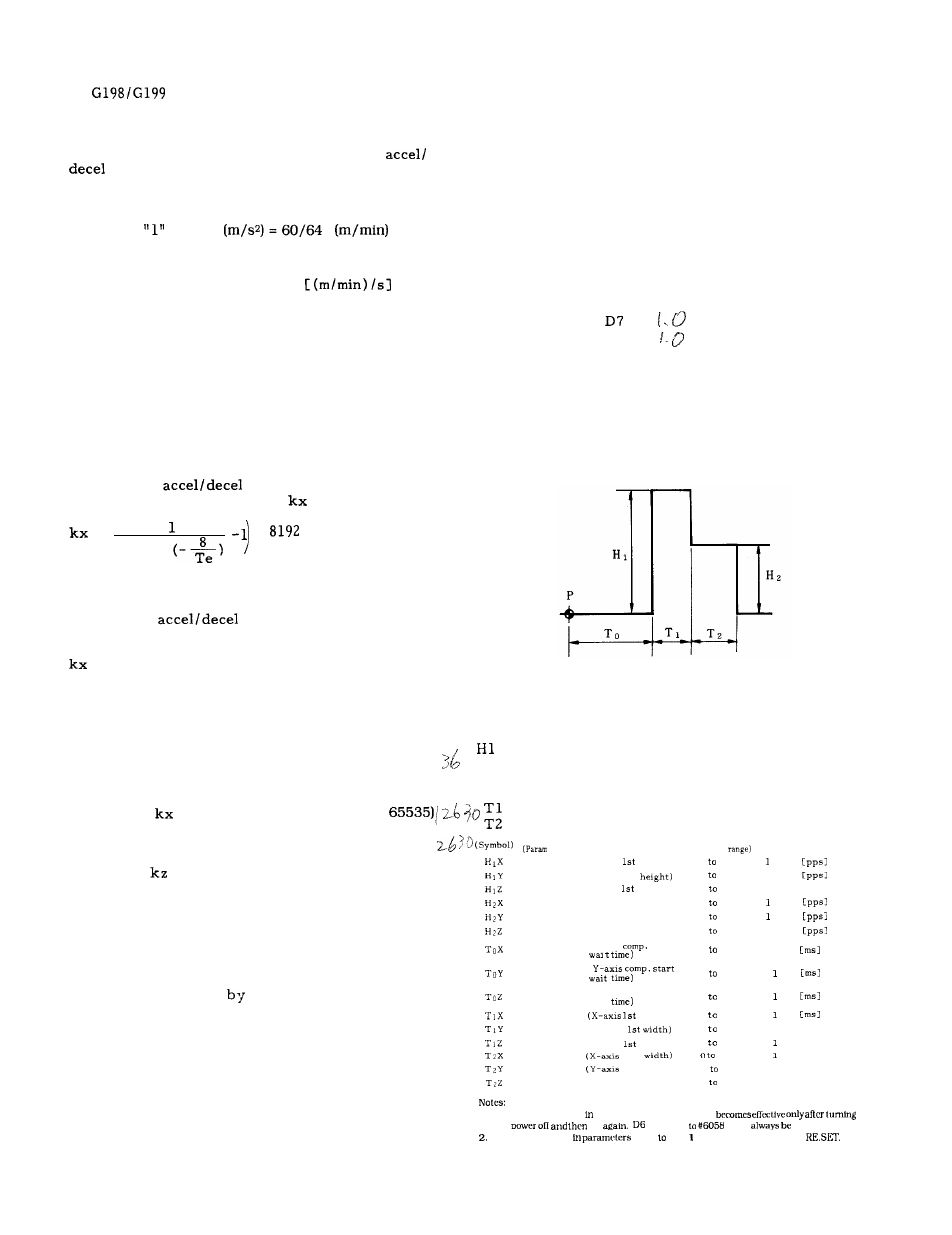
(b) Offset amount and timing
P
:
:
H2 :
TO :
coefficient
(X-axis)
– #6690 (O to
:
Servo follow-up
:
coefficient ky ‘(Y-axis)
– #6691 (O to 65535),
Servo follow-up
coefficient
( Z–axis)
- #6692 (O to 65535)
Servo follow-up
coefficient k4 (4th axis)
- #6693 (O to 65535)
2.14.3
CIRCULAR PROJECTION COMPENSATION
(1)
O v e r v i e w
When a circle is cut
the machining center, a
convex projection can be left at the switch point of
the quadrants.
This projection occurs because the lost motion
affects the machine to disturb immediate movement
when the move direction changed.
Start point of the circular projection
compensation
(Actually when the sign of the command is
reversed. )
Height of the 1st offset amount
Height of the 2nd offset amount
Wait time from the start point to the first
o f f s e t
Width of the 1st offset
Width of the 2nd offset
No. )
( Description)
(Setting
(Unit)
#6071
#6078
#6079
#6080
#6081
#6082
#6083
#6084
#6085
#6086
#6087
#6088
#6089
#6090
#6091
(X-axis
height)
(Y-axis 1st
(Z-axis
height)
(X-axis 2nd height)
(Y-axis 2nd height)
(Z-axis 2nd height)
(X-axis
start
(
( Z-axis comp. start
wait
width)
(Y-ax,.
(?-axis
width)
2nd
2nd width)
(Z-axis 2nd width)
0 255
= 500
0 255
1 = 500
O 255
1 = 500 [pp. ]
O 255
= 500
O 255
= 500
O 255
1 = 500
O 255
1 = 2
O 255
= 2
0 255
= 2
0 255
= 2
0 255
1 = 2 [m. ]
0 255
= z [m, ]
255
= 2 [m, ]
O 255
1 = 2 [m. ]
0 255
1 = 2 [m. ]
1.
Any change made parameters #6056 to #6058
the
on
of #6056
must
set o.
Any change
made
#6077 #609 becomes effective-by NC
1 2 9