Oi ( 1 i – Yaskawa J50M Instructions User Manual
Page 74
2.9.25 WORK COORDINATE SYSTEM SETTING C
(G52 TO G59)
t
(Cent’d)
(10 ) Correction of the work coordinate system shift
amount by external input
(a) The work coordinate system shift amount can be
corrected by external data input signals.
(b) The externally input axis correction amount is
added to all the G54
to G59 (J5) shift amounts
to make new shift amounts.
The setting of the
work coordinate system shift amount is not directly
corrected.
The work coordinate system is corrected
for external work coordinate system correction
amount.
Shift amount on actually moving work
coordinate system = External work coordinate system
correction amount + work coordinate system shift
amount setting.
(c) For rotary angle, the direct setting is
corrected.
Therefore, there is no external work
coordinate system correction amount.
(11 ) J-number monitor during execution of work
coordinate system shift
The pair addition number J can be monitored by
#6195, during execution of the work coordinate
system shift (G54 to
No J
#6195 = 1
●
? ” ”
2
J3
= 3
J4 . . . .
4
J5 . . . .
= 5
(12) Notes and remarks
(a) All the notes for the B-specifications
to
the C-specifications.
(b) Command the G54 to G59 commands under the
GOO to GO1 mode.
If commanded under other
modes, alarm
129” occurs.
(c) G68 and G69 cannot be used in this
specification. Executing G68 and G69 will cause
“alarm.
(d) The coordinate system rotation by the G54
command is canceled by the G52 command or by
setting O in the work coordinate system setting.
(e) The G28 /G30 commands during coordinate
system rotation under the G54 command, can
perform rotation at the intermediate positioning
point, but not on the reference point.
Coordinate system rotation is also not performed for
G53.
(f) The coordinate rotation plane of this specifi-
cation is fixed to the G17 plane.
2.9.26
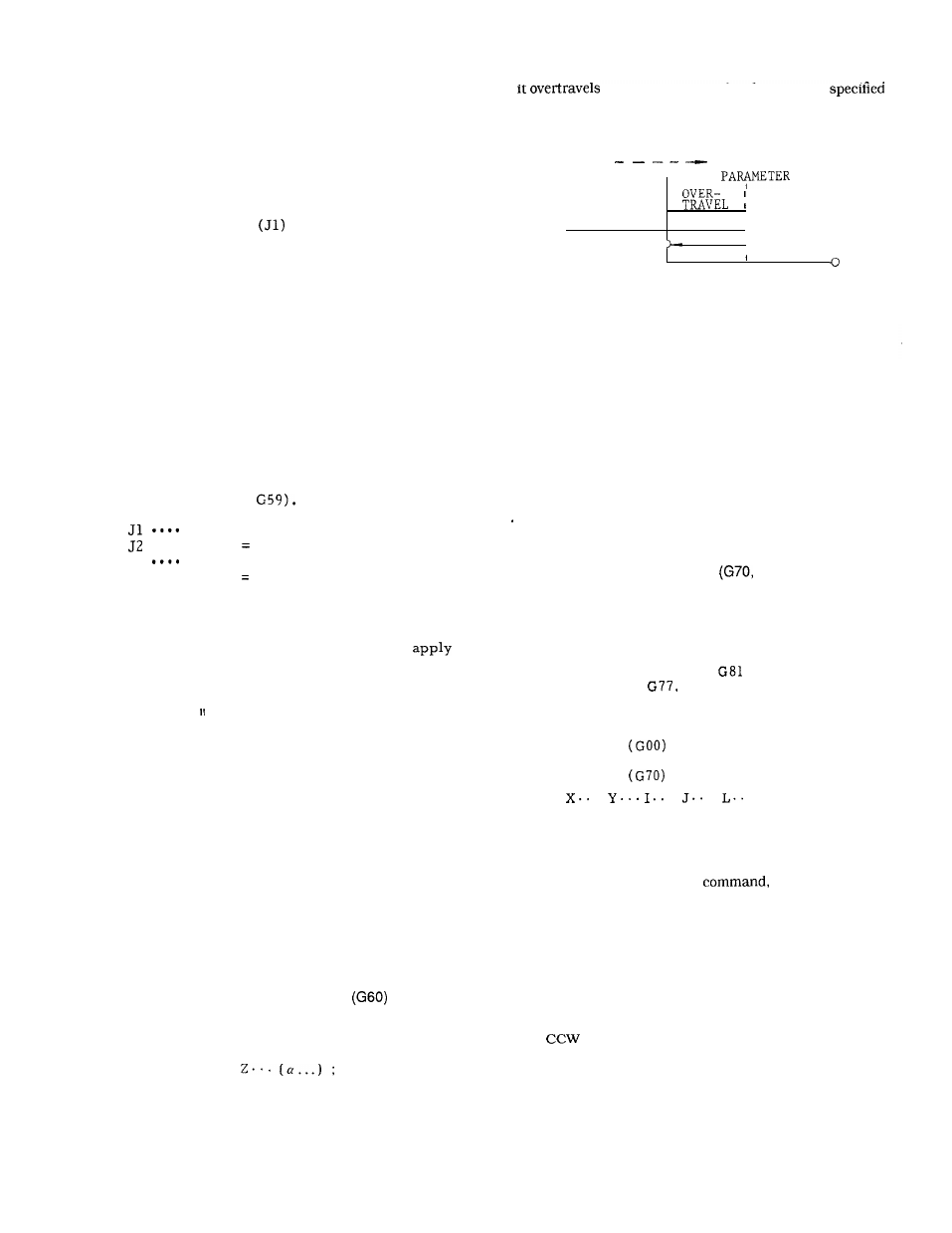
UNIDIRECTIONAL APPROACH
t
This function is effective to position the tool at
high accuracy .
G 6 0 x . . . Y . . .
With this command, the tool moves and stops at the
specified position. If the tool approaches the stop posi-
tion in the direction specified by the parameter (#6014),
the stop position by the amount
by parameters (#6436 - #6439), and then returns to the
specified position to stop.
DIRECTION SET BY
o
I
(
1
I
STOP
POSITION
F i g .
2.68
Notes :
. Unidirectional approach is effective in the canned cycle
mode. Shift by G76 includes unidirectional approach.
Cancel this function before executing G76 for safety pur-
poses.
. Unidirectional positioning is performed at the interim
point by G28 command.
When GOO is commanded in a G60 block, the latter
commanded G code is validated.
2.9.27
HOLE PATTERN CYCLES
G71 , G72)
t
With this function , when a radius and a center
angle are specified, the corresponding rectan-
gular coordinate positions are computed auto-
matically and the tool is brought to the required
positions.
This function is used in conjunction
with one of the canned cycles
through G89,
G73, G74, G76 and
With this function, the
bolt hole cycle , the arc cycle, and the line at
angle cycle are programmed.
The tool moves to
the position specified by a radius and an angle
in rapid traverse
.
. Bolt hole cycle
G70
.
.
.
. ;
With this command, the tool is positioned suc-
cessively at equally spaced L points on a cir-
cle with the center at X, Y and the radius of
1, starting at a point located on a line forming
J degree with X-axis. In the
X, Y : Coordinate of the bolt hole cycle, defined
I :
J :
L :
either in G90 or G91 mode.
Radius of the bolt hole circle, programmed in
a positive number and programmed with an
accuracy of the least input increment.
Angular position of the first hole, programmed
in degrees with an accuracy of O.001 degree.
direction is regarded positive.
Number of division of the circumference.
For the counter-clockwise sequence, positive
numbers are programmed, and vice versa.
66