Yaskawa J50M Instructions User Manual
Page 71
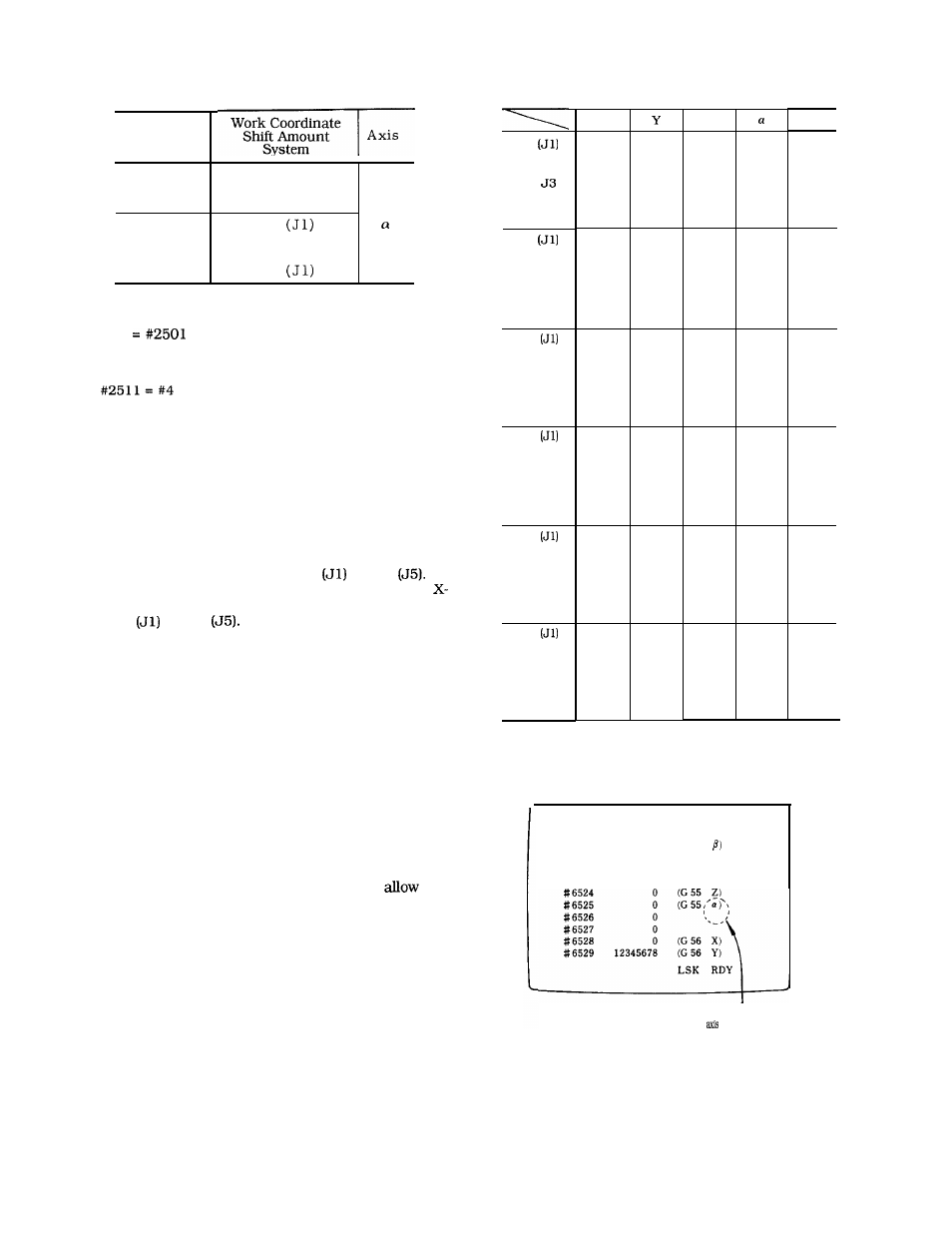
Table 2.26 (d)
Table 2.26 (e)
G54
J2
J4
J5
G55
J2
J3
J4
J5
R
#6521
#6705
#6741
#6777
#6813
#6527
#67 11
#6747
#6783
#6819
#6533
#6717
#6753
#6789
#6825
#6539
#6723
#6759
#6795
#6831
#6545
#6729
#6765
#680 1
#6837
#6551
#6735
#677 1
#6807
x
z
System
Variables
#6519
#6703
#6739
#6775
#6811
#6525
#6709
#6745
#6781
#6817
#6516
#6517
#670 1
#6737
#6773
#6809
#6523
#6707
#6743
#6779
#6815
#6529
#6713
#6749
#6785
#682 1
#6535
#6719
#6755
#6791
#6827
#6518
#6702
#6738
#6774
#6810
#6524
#6708
#6744
#6780
#6816
#6530
#6714
#6750
#6786
#6822
#6536
#6720
#6756
#6792
#6828
External work
coordinate system
correction amount
#6736
#6772
#6808
#6522
#6706
#6742
#6778
#6814
#2800
$2801
G54
.
G59
#2806
(d) Program examples
(i) #116
;
Command G54 (J 1) assigns the amount of work coordinate
system shift of X-axis as the common variable #116.
( i i )
Command G54 (J2) cancels the amount of work coordinate
system shift of X-axis and sets the contents of local vari-
able #4.
(10) Correction of the work coordinate system shift by an
external input
(a) The amount of work coordinate system shift can be
corrected by an external data input signal.
(b) The new amount of shift can be obtained by inputting
the amount of axis correction from the outside and adding
this to all of the shift values from G54
to G59
For example, inputting the amount of shift for the
axis will correct X-axis shift amounts for all commands
from G54
to G59
(11) Notes and remarks
(a) The notes in Specification A are also applicable to
Specification B.
(b) Use the G54 to G59 ; commands in the GOO or GO1
mode. Alarm “129” will occur if used in any other mode.
2.9.25
WORK COORDINATE SYSTEM SETTING C
(G52 TO G59)
t
(1) Outline of work coordinate system setting expansion
function
The rotary angle can be set in the work coordinate system
setting when commanding G54 to G59, to perform the
coordinate system rotation at the same time. The J2 to J5
commands of G54 to G59 are also expanded to
set-
ting of the 4th axis.
(2) The item on the rotary angle is added to the work coor-
dinate system setting. The 4th axis can be set to all the
work coordinate systems at the same time. See Table 2.26
(e) for the setting numbers.
G56
J2
J3
J4
J5
G57
J2
J3
J4
J5
G58
J2
J3
J4
J5
G59
J2
J3
J4
J5
#6528
#6712
#6748
#6531
#6715
#6751
#6787
#6823
#6537
#672 1
#6757
#6793
#6829
#6820
#6718
#6754
#6826
#6540
#6724
#6760
#6796
#6832
#6546
#6730
#6766
#6802
#6838
#654 1
#6725
#676 1
#6797
#6833
#6547
#673 1
#6767
#6803
#6839
#6542
#6726
#6762
#6798
#6834
#6548
#6732
#6768
#6804
#6840
#6543
#6727
#6763
#6799
#6835
#6549
#6733
#6769
#6805
#6841
(3) Setting command display
SETTING
O
1234 N 1234
#6520 –12345678
(G54
#6521
3000
(G54 R)
# 6522
0
(G 55 X)
# 6523
0
(G 55 Y)
# 6524
# 6525
A, B, C. U,
V or W is displayed by the
4th specification.
Fig, 2.67
63