Yaskawa J50M Instructions User Manual
Page 94
2.9.30 ABSOLUTE/lNCREMENTAL PROGRAMMING
(G90, G91 ) (Cent’d)
Incremental designation
In the block including G91 and in the subsequent
blocks, data area is regarded as incremental values.
G91 GO1 X.. .
z.. . ;
. . .
. . . Incremental designation
I
Y3
G90 :
I
I I
Incremental
Absolute
Fig. 2.76
G90,
are modal G codes of 03 group.
. If both
and G91 are programmed in the
same block, the G code which was programmed
last is valid.
Note :
.
The initial state of these G codes when the pow-
er is turned on can be designated
parameter
Parameter(
Initial state
I
G 90
G 91
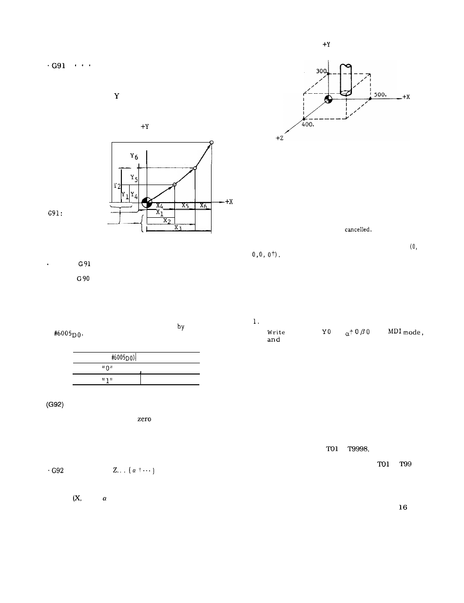
2.9.31 PROGRAMMING OF ABSOLUTE ZERO POINT
Programming the absolute
point before program-
ming movement command is required. When an
absolute zero point is programmed, one absolute coordi-
nate system is determined, and all absolute movement
commands programmed thereafter will move the tool on
the programmed coordinate.
X.. . Y.. .
;
With this command, the current position of the tool is
programmed in the control as absolute coordinate
point
Y, Z, t). That is, program the distance
(with sign) from the desired absolute zero point (O, O,
0, 0 t ) to the current position. In other words, G92
command is for designating the position of the
“absolute zero point”.
EXAMPLE
G92 X500.
Y300.
2400. ;
I
Fig.
2.77
. G92
is a G code of non-modal group which is
valid only in the programmed block. It is not
possible to program other G codes, F, M, S,
T , B
+
codes in the same block.
Notes :
In
principle , program G92 in the state where
all tool offset modes are
. When the power is turned on , the current posi-
tion of the tool is set as absolute zero point
Make sure to reprogram absolute co-
ordinate by G 92 before executing the automa-
tic operation.
The programmed absolute zero point is not af-
fected by reset operation. Perform any of the
following operations for resetting the absolute
zero point.
Use ORG key (see 4.1. 9)
2.
G92 XO
20
; in
then execute . “
3.
Turn the power off and on again
2.9.32 TOOL LIFE CONTROL (G1 22, G123)
2.9.32.1
TOOL LIFE CONTROL
The tools are classified into groups and tool life
(usage time, total usages or usage distance) is set for
each group. This is a function to give commands for
tool groups from the part program and to select the
next tool in the same group, which has been sequen-
tially arranged, when the fixed life expires.
(1)
Maxtmum number of tools to be controlled . . ...256
Of the tool numbers from
to
256 can be regis-
tered as tools for tool life control. If T code commands are
given with two digits, tool numbers from
to
can
be used.
(2)
Number of groups that can be registered and the
number of tools that can be registered per group.
Maximum number of groups . . . . . . . 128
Maximum number of tools per group . . . . . . .
The maximum controllable number of tools is 256.
Note :
Different number of tools can be set for each
group such as 12 in group 1, 8 in group 2.
86