Yaskawa J50M Instructions User Manual
Page 25
. Mirror image external input function
(a) Overview
In addition to the conventional mirror image
function, the mirror image execution mode can also
be set when power is turned on, or reset, by
setting the corresponding parameter.
When the
mode is the mirror image execution mode (power on
or reset, ) the parameter can be set to select the
command mirror image at the G28 intermediate point
or not.
(b) How to use the function
(i) Upon power ON or upon reset
#6005,
O: M94 mode (mirror image off)
1: M95 mode (mirror image on)
(ii) Upon power ON, when it is M95 mode (#6005,
i s “ l . ” )
#6005,
O: Commands mirror image at the
intermediate point
1: Does not command mirror image at
the G28 intermediate point
Note : The specifications are the same as the
conventional specifications, when #6005,
is “O. ”
Therefore, turn off mirror image by M94, when
commanding G28, or G29 under this mode.
E r r o r
if
t u r n e d
(c) Program example
Example of commanding mirror image on the G28
intermediate point
Program example (mirror image of X-axis only is
on)
REFERENCE POINT
X-AXIS MIRROR
‘
-
IMAGE ON
100
, / ”
PROGRAM COMMAND
50
- \ .
I
x
100
–40 o
40
100
Note : When commanding axis designation under the
mirror image mode
by m code, stop the
ahead by parameter (#61 16) of the set/reset M codes.
2.8.6 CIRCULAR PATH MODE ON/OFF ON
TOOL RADIUS COMPENSATION C
M96) t
M code
Meaning
M 96
Tool radius compensation circular
path ON.
Tool radius compensation circular
M 97
path OFF.
(Execution of intersection point)
Note:
When power is applied or the control is
reset, the control is in the state of M code
marked
.
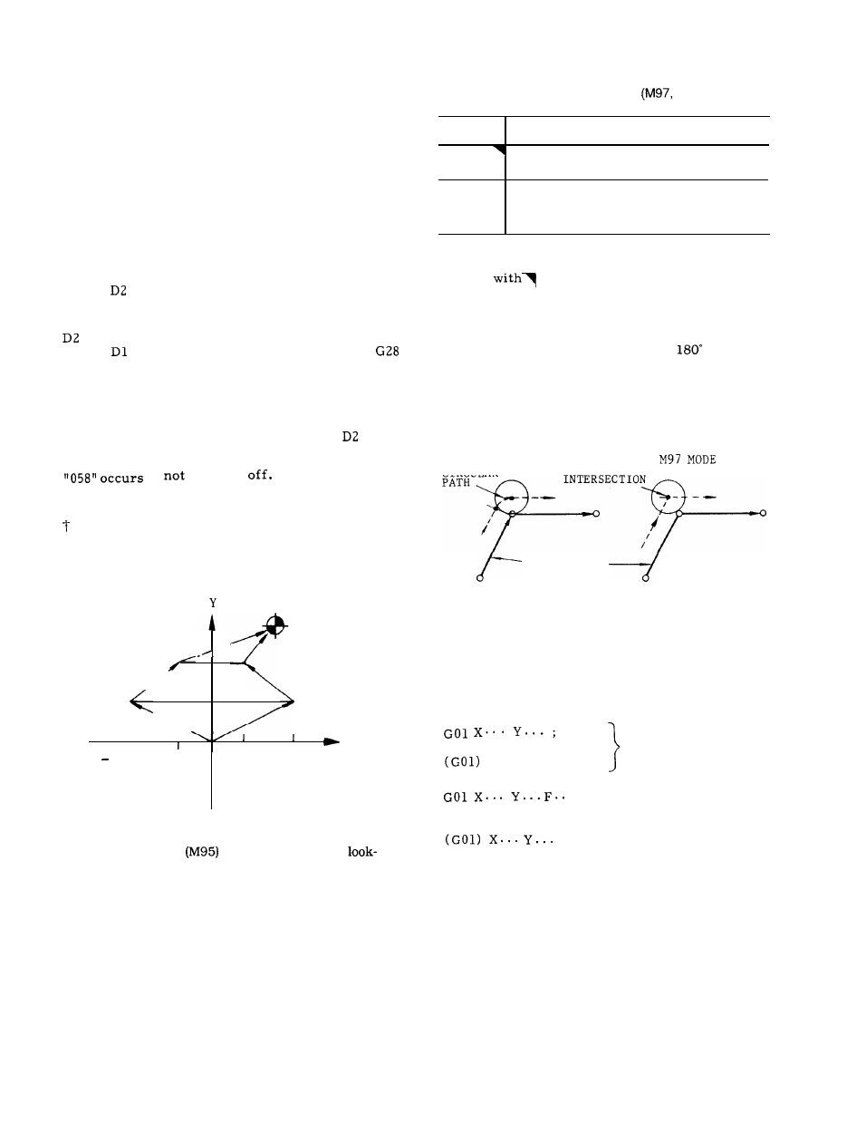
In the G41 or G42 tool radius compensation mode,
when M96 is given, the tool moves along a circular
path around a corner with an angle of
or larger.
In the M97 mode, the tool does not move along a
circular path at the corner, but moves along two
intersecting straight lines intersecting at a calculated
intersecting point shifted from the programmed
contour by the tool radius.
M96 MODE
CIRCULAR
PROGRAMMED
CONTOUR
Fig. 2.10
M96 and M97 are modal. When the power is
turned on, M96 takes effect.
M 96 and M97 are effective on the following
move command blocks.
X.. . Y.. . M96 ;
. ;
M96 (or M97) ;
;
}
Effective from
the corner of
these 2 blocks
Effective from
the corner of
these 2 blocks
17