Yaskawa J50M Instructions User Manual
Page 178
I
5.1.21 DISPLAY
LOCK SWITCH
This switch functions to stop updating the posi-
tion display, or to stop move command pulses to
the servos.
This switch cannot be set unless the
machine is stopped at block end or temporarily
stopped by FE ED HOLD pushbutton.
OFF
DISPLAY
LOCK
LOCK
5.13
“OFF”
operation is made at “OFF” position in both
manual and automatic operation.
The machine
and the position display operate according to the
command by automatic operation or manual
tion.
“DISPLAY LOCK”
This position is used to exclude the axis movement value
from the position display. 3rd/4th axis external current
position display is not updated, though the machine
moves.
“MACHINE LOCK’
Setting the switch at MACHINE LOCK inhibits axis move-
ment including Reference Point Return. The position dis-
play is updated.
M-, S-, and T-functions are executed.
This position is selected to preset the display or to check
the tape data by normal operation.
If MACHINE LOCK is on, reference point return is not
executed. Do not operate this switch unless the machine
is in the stopped state. That is, it is changed only during
block stop or feed-hold.
Note :
When operation is restarted with MACHINE LOCK off
after operation with MACHINE LOCK on, since the NC
operates with the coordinate value obtained immediately
before MACHINE LOCK off as reference, motion is made
in which the coordinate system is shifted by MACHINE
LOCK moving amount when an absolute command
is provided. Therefore, set again to the proper coordinate
value suitable for the machine position at MACHINE
LOCK
Off.
5.1 .22A Z-AXIS COMMAND NEGLECT SWITCH
The switch is used for
run operation or draw-
ing–check operation on the X-Y
Turning
on the switch causes the Z-axis in MACHINE
LOCK condition.
The Z-axis movement is in-
hibited, though the position display is updated.
Operate the switch when the machine is stopped.
That is , the switch does not function except when
the machine is stopped at the block end by SIN-
GLE BLOCK switch or temporarily stopped
FEED HOLD pushbutton.
Note :
When operation is restarted by CANCEL off after opera-
tion by Z-axis CANCEL on, since the NC operates with
the coordinate value obtained immediately before CAN-
CEL off as reference, motion is made in which the coordi-
nate system is shifted by Z-axis CANCEL moving amount
when an absolute command
provided.
Therefore, set Z-axis again to the proper coordinate value
suitable for the machine position at CANCEL off.
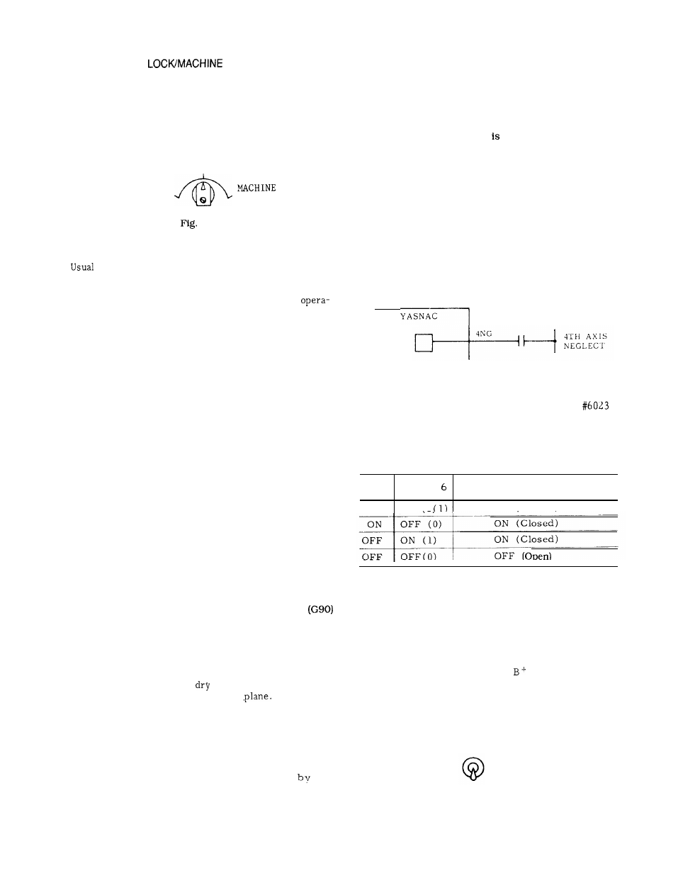
5.1 .22B 4TH AXIS NEGLECT INPUT
(1) When the POWER ON switch is pushed with
a 4th axis neglect input on (contact is closed) ,
the system is equivalent to one without the 4th
axis control.
If motion along the 4th axis is
commanded in this state,
the machine remains
motionless along the 4th axis, but the position
display indicates the supressed motion. (Machine
lock state) .
Fig. 5.14
(2) The ON /OFF switching of parameter
D6 is equivalent to the ON /OFF switching of the
4th axis neglect input.
The result of these two
is determined by their logical OR.
Table 5.6
4NG
Logical
O R
Input
#6023 D
( 4GNC for 4th Axis Neglect)
ON
ON
O N ( C l o s e d )
Note : When 4NG input or #6023 D6 is switched over, be
sure to switch on the power supply again.
Otherwise, the switching is ineffective.
5.1.23 M-FUNCTION LOCK SWITCH
(AUXILIARY FUNCTION LOCK)
When the M-FUNCTION LOCK switch is on, it
ignores the M, S, ‘T, and
commands. To
check the tape data, the operation by the switch
is used in combination with MACHINE LOCK
function .
AUX
FUNCTION
LOCK
OFF
Fig. 5.15
170