Yaskawa J50M Instructions User Manual
Page 41
NOO1
I
NOl O
PO1O1OO
QO1O15O:
I
I
O Level.
Program No. 0050
N1OO
I
I
G25 POO11O2OO
QOO11O25O:
I
I
I
N200
I
I
I
N225
N250
P65;
N300
I
I
I
I
I
I
I
N400
“99;
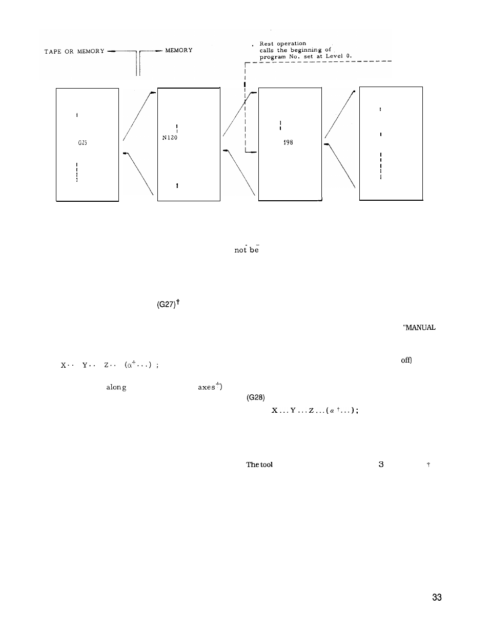
3rd
Level
1st Level
2nd Level
Program No. 0001
Program No. 0011
program No. 0065
Notes :
1. M98 can be used in a program
copied with
G25.
F o u r l e v e l s m a y
e x c e e d e d e v e n
when using G25 with M98.
2. Care should be taken when jumping to a
different L level with M99 since execution will
become endless with no means of escape.
2.9.14 REFERENCE POINT CHECK
This function is for checking the correct return
of the tool to the reference point after performing
a cycle of operation in accordance with a program
which starts at the reference point and ends at
the reference point.
G 2 7
.
.
.
With this command, the tool moves towards the
specified position
the three axes ( 4
simultaneously but independently, and after the
arrival at the specified point, the point is check-
ed for the conformity to the reference point. If
any of the axes is omitted in the command, the
tool does not move in that axis and no check is
made in that axis.
If the point is in conformity with the reference
point, the reference point return lamp lights.
If the tool is correctly in the reference point in
all the axes, automatic operation is performed
further, but if the tool is not in the reference
point even in one axis, this is regarded as an
error ( alarm 241 - 244 display) , and the auto-
matic operation is interrupted.
(Cycle start
lamp goes off. )
If G27 is commanded in the tool offset mode, the
tool return point is also offset. Cancel the tool
offset mode when commanding G27.
Reference point as meant here is a freed point relative to
the machine to which the tool returns by the manual
reference point return motion or by G28 automatic
reference point return motion. Refer to 5.2.1,
RETURN TO REFERENCE POINT’ on page 174. The
mirror image function can be applied to the G27
command. To avoid non-conformity errors, clear the
mirror image mode with M94 (Mirror image
before
commanding G27.
2.9.15
AUTOMATIC RETURN TO REFERENCE POINT
t
G 2 8
With this command, the tool is sent back to the reference
point. The tool moves towards the specified points in
rapid traverse, and automatically stops at the reference
point.
moves simultaneously in up to axes (4 axes ).
However, the tool will not move in the direction of the
axis for which a coordinate instruction is omitted.