Yaskawa J50M Instructions User Manual
Page 181
YASNAC
I
SWITCH
Notes:
I
+x
TRAVERSE
-Y RATE
- z
I
5.23
i.
The external deceleration function is ineffec-
tive on feedrate specified in mm per revolu-
tion of the spindle (mm/rev) .
ii.
It is also ineffective on the HANDLE feed.
5.1.31 3RD TO 5TH STORED STROKE
t
By adding the stored stroke limit function
G23), it
is possible to set the 3rd, 4th and 5th prohibited areas
simultaneously. However, selecting the ON/OFF state of
this function must be by means on an external signal.
(1) 3rd, 4th and 5th prohibited areas
The 3rd, 4th, and 5th prohibited areas can be
set by means of the parameters “Address Stroke
Limit -3. -4. -5”
3RD PROHIBITED AREA
4TH PROHIBITED AREA
1
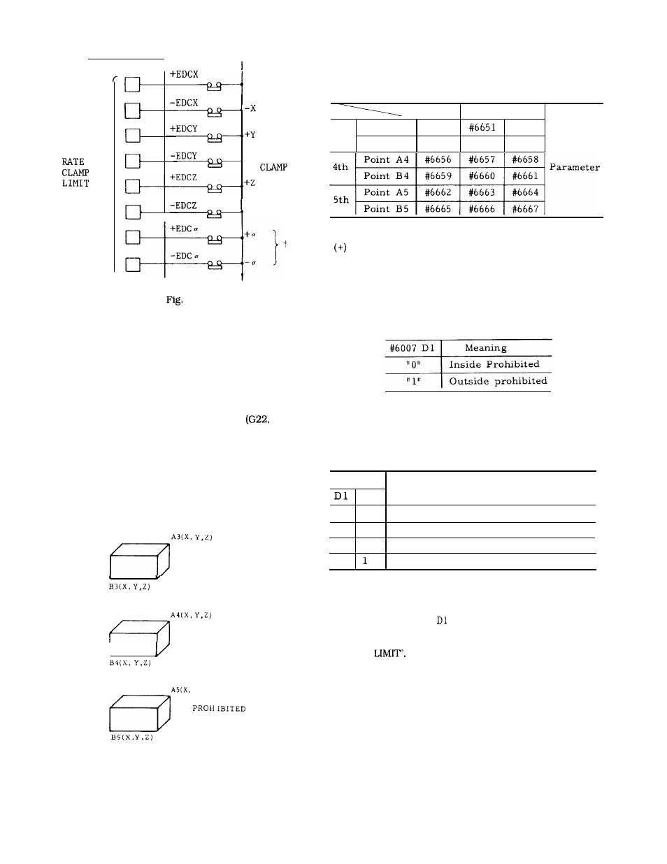
(2) The parameters for setting prohibited areas
are as shown in the table below.
Table 5.7
I
x
Y
I
z
Point A 3
3rd
#6650
#6652
Point B 3
#6653
#6654
#6655
Point A sets the boundary value on the positive
side of the machine coordinate system and
point B sets the boundary value on the negative
(-) side.
(3) Setting of the inside or outside of the 3rd,
4th and 5th prohibited areas as the prohibited
area is performed simultaneously by the following
parameters.
(4)
The following external signals are used to
turn on area check of either the 3rd or 4th
prohibited area.
Table 5.8
#1312
Meaning
DO
o
0
3rd to 5th prohibited area check OFF
o
1
3rd prohibited area check ON
1
0
4th prohibited area check ON
1
5th prohibited area check ON
O: Contact open
1: Contact closed
When this function is not used, set input
signal #1312 DO and
to “O. ”
Note: Same
as the notes for section 2.9.12 “STORED
STROKE
Y, Z,)
5TH
AREA
173